CANOpen Setup Guide
Introduction
This guide demonstrates a simple usage of CANOpenIOServer in CDP Studio, the independent automation software for open PC-based real-time distributed control systems, to send out two int values with RPDO to CAN node and receive two int values with TPDO telegram from CAN node (these 8 bytes of raw data also are the maximum RPDO/TPDO telegram size in CANOpen). To achieve this two output source signals are added to the application component named "OutInt1" and "OutInt2". To show received values in the same place two input destination signals are added to the application component named "InInt1" and "InInt2". Then two CANOpenUDPIOServer components are added to the application, one of them is set to be a slave to emulate the CANOpen bus. CANOpenIOServer.Node is added to both IOServers with the same address. Then TPDO telegram is added to the Nodes with two CDPSignalChannel<int> objects to represent the two int values in the telegrams. Needed routings are set to move the values between the channels in telegrams and source/destination signals. The system is then deployed on localhost, run and connected to test and monitor the example system.
Configuring the Example
Setup Example Control Signals
- Click Welcome mode to go to the Welcome Page
- In the Projects tab, under Create Project, Click New Project
- Select CDP System and click Choose...
- Type in "CANDemo" in the Name text field. Click Next >
- Click Next > to select the default Framework version
- Choose Application Type Console and Application Name CANDemoApp.
- Click Finish
- Select Configure mode.
- Select the CANDemoApp that resides under CANDemo in the Project tree.
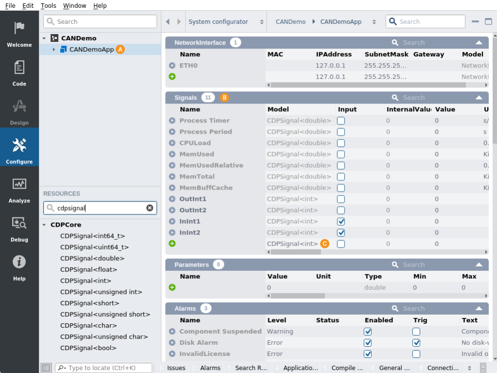
- Double-click on the Signals section table header to fully expand the section and show all signals.
- Select CDPSignal<int> for Model in Signals section table last row.
- Click button to add the signal. Add four signals of int type.
Note: It is faster to add multiple int type Signals by filtering for Signal in Resources then right click on CDPSignal<int> and selecting Add Multiple....

- Change the signal names by double-clicking on the current name and editing it to "OutInt1", "OutInt2", "InInt1" and "InInt2", mark the Input checked for InInt1 and InInt2 signals.
Note: Input is checked for InInt1 and InInt2 because later the example routes the signal's value from the IOServer.
Add CANOpenUDPIOServer and MasterNode/SlaveNode
- Make sure that CANDemoApp that resides under CANDemo in the Project tree is still selected.
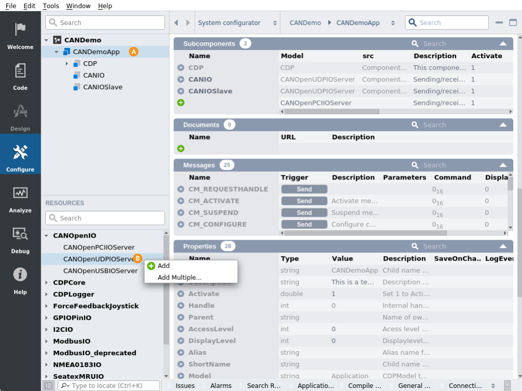
- In the Resource tree, expand the CANOpenIO resource.
- Right-click and select Add Multiple... on CANOpenUDPIOServer, set Base name to "CANIO", set Count to 2.
- Rename CANIO1 to "CANIOSlave".

- Expand CANDemoApp and select CANIO in the Project tree.
Note: Resources are always added as children to the currently selected item in the Project tree (only applicable resources for the selected item are shown).
- From the Resource tree, right-click and select Add on MasterNode to add it to the CanInterface section table in the CANIO component.
- Select CANIOSlave in the Project tree.
- From the Resource tree, right-click and select Add on SlaveNode to add it to the CanInterface section table in the CANIOSlave component.
- Double-click on CANIOSlave Properties section table header.
- Find Slave option in Properties section table and set it.
- Find RemotePort and LocalPort and swap their values.
Configure CANIO Component's MasterNode
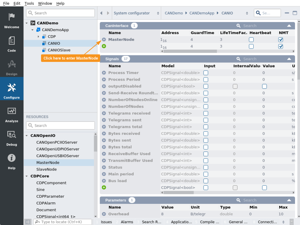
- Select CANIO in the Project tree and scroll to CanInterface section table.
- Click button in front of MasterNode.

- From the Resource tree, right-click and select Add on TPDO.
Note: For MasterNodes, TPDO is a received telegram so the Input Property is Set.
- Click button in front of TPDO to enter.
- From the Resource tree, right-click and select Add Multiple... on CDPSignalChannel<int>, set Base name to "OutInt1" and Count to "2", Click OK.
Note: The Input Property is not set on these channels, because the channels are added to a TPDO on a MasterNode. The values in these channels will be sent to the added InInt signals in the application.
Configure CANIOSlave Component's SlaveNode
- Select CANIOSlave in the Project tree and scroll to CanInterface section table.
- Click button in front of SlaveNode.
- From the Resource tree, right-click and select Add on TPDO.
Note: For SlaveNodes, TPDO is a transmitted telegram so the Input Property is not Set.
- Click button in front of TPDO to enter.
- From the Resource tree, right-click and select Add Multiple... on CDPSignalChannel<int>, set Base name to "InInt1" and Count to "2", Click OK.
Note: The Input Property is set on these channels because the channels are added to a TPDO on a SlaveNode. We will route emulated values to these channels from added OutInt signals in the application.
- Edit the Routing Property on InInt1 and InInt2 channels to "CANDemoApp.OutInt1" and "CANDemoApp.OutInt2".
Finish Routing of Added Application Signals
- Select CANDemoApp in the Project tree.
- Double-click on the Signals section table header to fully expand the section and show all signals.
- Set the Routing Property of InInt1 and InInt2 Signals to "CANDemoApp.CANIO.MasterNode.TPDO.OutInt1" and "CANDemoApp.CANIO.MasterNode.TPDO.OutInt2".
How to Run the Tutorial
To run the tutorial from CDP Studio, select Configure mode, right-click on the system project and select Run & Connect. See the Running and Connecting to the System tutorial for more information.
Verify the Demo System
Set the OutInt1 and OutInt2 Signals in CANDemoApp to monitor the signal values looping through: CANDemoApp > CANIOSlave > CANIO > CANDemoApp
Get started with CDP Studio today
Let us help you take your great ideas and turn them into the products your customer will love.