GPIO Setup Guide
Introduction
This guide demonstrates how to create a simple application for reading a single input and controlling a single output of a Raspberry PI 3 Model B with CDP Studio, the independent automation software for open PC-based real-time distributed control systems.
Setting Up the Hardware
Before creating the CDP application the physical input and output devices must be set up. For this example, a simple pushbutton and an LED will be used.
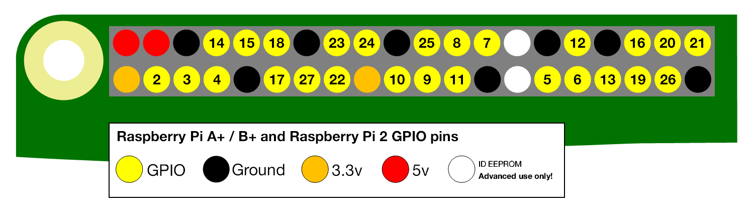
- For the input, connect one end of a pushbutton to the GPIO pin 18 and the other end to the 3.3V pin.
- For the output, connect one end of an LED with a resistor to the GPIO pin 17 and the other end to the ground.
Refer to the following image for the GPIO pin layout of the Raspberry PI.
Creating the Control System in CDP Studio
Next, we need to create a system to control the LED according to the user input from the pushbutton.
Setting Up the Control System
Follow these steps to create the system:
- Create a new CDP Studio system and name it GPIOTest
- Add a GPIOServer to the default application
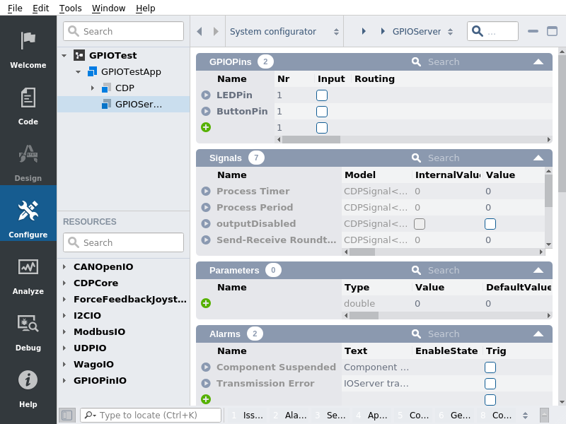
- Add a GPIOPin to the GPIOServer and rename it to LEDPin
- Add another GPIOPin to the GPIOServer and rename it to ButtonPin
After completing these steps the system should look like this:
Configuring the Control System
Next, we need to configure the system so that CDP knows which GPIO pin we want to control and which one we want to get input from. We decided to connect the LED to pin 17 and the pushbutton to pin 18, so we have to configure our GPIOPins accordingly.
- Set LEDPin "Nr" property to 17
- Set ButtonPin "Nr" property to 18
This ties our GPIOPins to specific physical pins on the Raspberry PI. Now we need to define whether the pins are input or output pins.
- Check the "Input" checkbox of LEDPin
- Leave the "Input" checkbox of ButtonPin unchecked
Note: Remember that the "Input" checkbox should be viewed from the perspective of CDP meaning that if it should accept inputs from CDP then the checkbox should be checked. If it is itself an input to CDP (like a sensor or a pushbutton) and can only be read by CDP then the "Input" checkbox should stay unchecked.
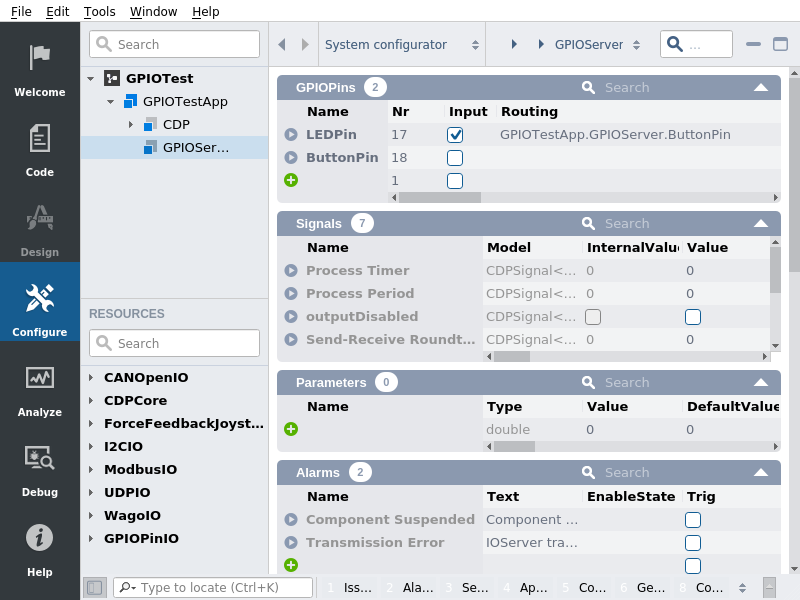
Lastly, we need to add a routing to the LEDPin so it takes its input from the button Simply set the LEDPins routing to "GPIOTestApp.GPIOServer.ButtonPin".
The final configuration should look like this:
Testing the System
The system is ready for testing. Connect the Raspberry PI to the network if it is not already and deploy the system onto it. When the system starts then pushing the button should light up the LED.
Get started with CDP Studio today
Let us help you take your great ideas and turn them into the products your customer will love.