UDP Setup Guide
Introduction
This guide demonstrates a simple usage of UDPIOServer to send out a two-byte binary UDP packet with boolean and char values and receive the UDP packet in CDP Studio, the independent automation software for open PC-based real-time distributed control systems. To achieve this two output control signals are added to the application component named "OutBool" and "OutChar". To show the received value in the same place two input signals are added to the application component named "InBool" and "InChar". Then UDPIOServer is added to the application. Output and input packets with channels representing the packet format are added to the UDPIOServer. Needed routings are set to move the values between the channels in packets and control signals. The system is then deployed on localhost, run and connected to test and monitor the example system.
Configuring the Example
Setup Example Control Signals
- Click Welcome mode to go to the Welcome Page
- In the Projects tab, under Create Project, Click New Project
- Select CDP System and click Choose...
- Type in "UDPDemo" in the Name text field. Click Next >
- Click Next > to select the default Framework version
- Choose Application Type Console and Application Name UDPDemoApp.
- Click Finish
- Select Configure mode and go to the Table Editor tab.
- Select the UDPDemoApp that resides under UDPDemo in the Project tree.
- Double-click on the Signals section header to fully expand the section and show all signals.
- Select CDPSignal<bool> for Model in the Signals section table last row.
- Click button twice to add two signals of boolean type.
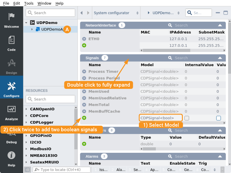
- Change the signal names by clicking on the current name and editing it to "OutBool" and "InBool", mark the Input checked for InBool signal.
Note: Input is checked for InBool because later the example routes the signal's value from the input packet.
- Select CDPSignal<char> for Model in the Signals section table last row.
- Click button twice to add two signals of char type.
- Change the signal names by clicking on the current name and editing it to "OutChar" and "InChar", mark the Input checked for InChar signal.
Note: Input is checked for InChar because later the example routes the signal's value from the input packet.
Add UDPIOServer and Packets
- In the Resource tree, expand the UDPIO resource.
- Right-click and select Add on UDPIOServer to add it to UDPDemoApp.
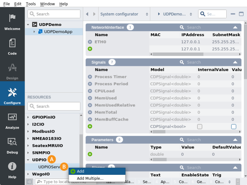
- Expand UDPDemoApp and select UDPIOServer in the Project tree
Note: Resources are always added as children to the currently selected item in the Project tree (only applicable resources for the selected item are shown).
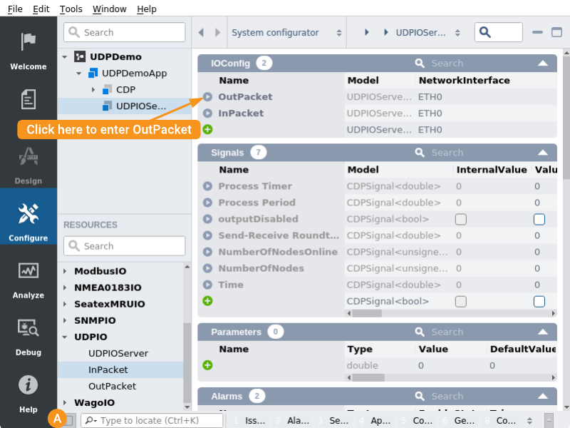
- From the Resource tree, right-click and select Add on OutPacket to add it to the IOConfig section in the UDPIOServer.
- From the Resource tree, right-click and select Add on InPacket to add it to the IOConfig section in the UDPIOServer.
Navigate into Output Packet
- The Navigation bar with the Project tree and Resource tree can be hidden from the Hide sidebar button
- Click button in front of OutPacket in the IOConfig section. This will enter the packet.
Configure Output Packet
- Select CDPSignalChannel<bool> for Model in the CDPChannel section table last row.
- Click button to add channel of boolean type. Name it "OutBool", set Nr to "0", mark Input check-box and set Routing to "UDPDemoApp.OutBool".
Note: Input is checked because the signal's value is routed from another signal.
- Select CDPSignalChannel<char> for Model in the CDPChannel section table last row.
- Click to add channel of char type. Name it "OutChar", mark Input check-box and set Routing to "UDPDemoApp.OutChar".
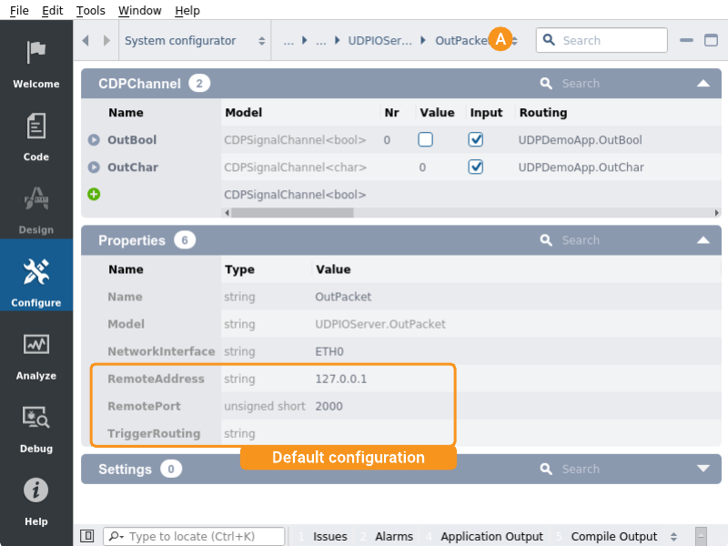
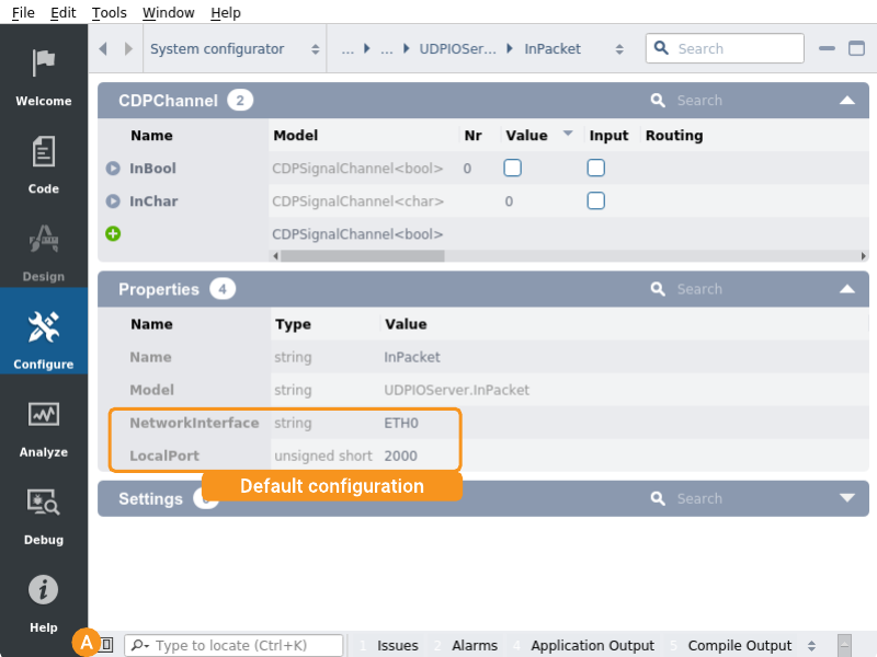
Note: We will use the OutPacket default configuration for the purposes of the example, but in most cases the properties need to be adjusted.
- In Navigation bar click on OutPacket and select InPacket from opened drop-down.
Configure Input Packet
- Select CDPSignalChannel<bool> for Model in the CDPChannel section table last row.
- Click to add a channel of boolean type. Name it "InBool", set Nr to "0".
- Select CDPSignalChannel<char> for Model in the CDPChannel section table last row.
- Click button to add a channel of char type. Name it "InChar".
Note: We will use the InPacket default configuration for the purposes of the example, but in most cases the properties need to be adjusted.
- The Navigation bar with Project tree and Resource tree can be shown again from Hide sidebar button.
Setup Routing for Example Control Signals
- Select the UDPDemoApp that resides under UDPDemo in the Project tree.
- In Signals section edit InBool signal's Routing to "UDPDemoApp.UDPIOServer.InPacket.InBool"
- In Signals section edit InChar signal's Routing to "UDPDemoApp.UDPIOServer.InPacket.InChar"
How to Run the Tutorial
To run the tutorial from CDP Studio, select Configure mode, right-click on the system project and select Run & Connect. See the Running and Connecting to the System tutorial for more information.
Verify That It Works
When selecting the UDPDemoApp from the Project tree it is possible to set the Value on OutBool and OutChar causing the routed InBool and InChar to change.
Note: What happens is that when OutBool is changed the value is routed in OutPacket OutBool that is sent out on UDP to 127.0.0.1:2000 then InPacket receives the value and InBool in UDPDemoApp routes the value from InPacket InBool signal.
Get started with CDP Studio today
Let us help you take your great ideas and turn them into the products your customer will love.