Creating a Multivariable Interface
Introduction
The purpose of this example is to demonstrate how a CDPPort object can be used to group related values that make up a data interface in CDP Studio, like in PLC STRUCT type in IEC 61131-3 languages used for input/output variables allowing simplified multi-value connections.
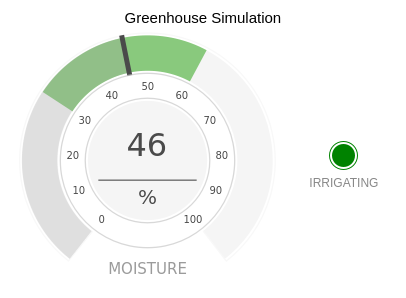
In this example a greenhouse controller uses the port to monitor soil moisture and start or stop irrigation if needed.
How to Run the Example
To run the example from CDP Studio, open Welcome mode and find it under Examples. Next, in Configure mode right click on the library project and select Build, then right click on the system project and select Run & Connect. See the Running the Example Project tutorial for more information.
Project Overview
This example includes:
- A library project containing one port and two components:
- IrrigationControlPort - contains the properties used to control the greenhouse soil moisture.
- Controller - reads Moisture value and if necessary, starts or stops Irrigation of the soil.
- EnvironmentSimulator - used to make this example run without actual hardware. Simulates soil drying and increases soil moisture if irrigation is in progress.
- A system project containing two applications:
- GreenhouseApp - contains the Controller and EnvironmentSimulator components which are connected by a IrrigationControlPort.
- GUI - contains widgets to display current soil moisture and to show whether irrigation is in progress.
As mentioned, the CDPPort is used to group related values that make up an interface to a component:
class IrrigationControlPort : public CDPPort
{
public:
    void Create(const char* shortName, CDPComponent* parent) override;

    CDPProperty<double> Moisture;
    CDPProperty<bool> Irrigation;
};
The CDPPort not only groups related values together but also handles connecting both the inputs and outputs, so the user can write code like this:
if (IrrigationControl.IsConnected())
{
    if (IrrigationControl.Moisture <= MinDesiredMoisture)
        IrrigationControl.Irrigation = true;
    else if (IrrigationControl.Moisture >= MaxDesiredMoisture)
        IrrigationControl.Irrigation = false;
}
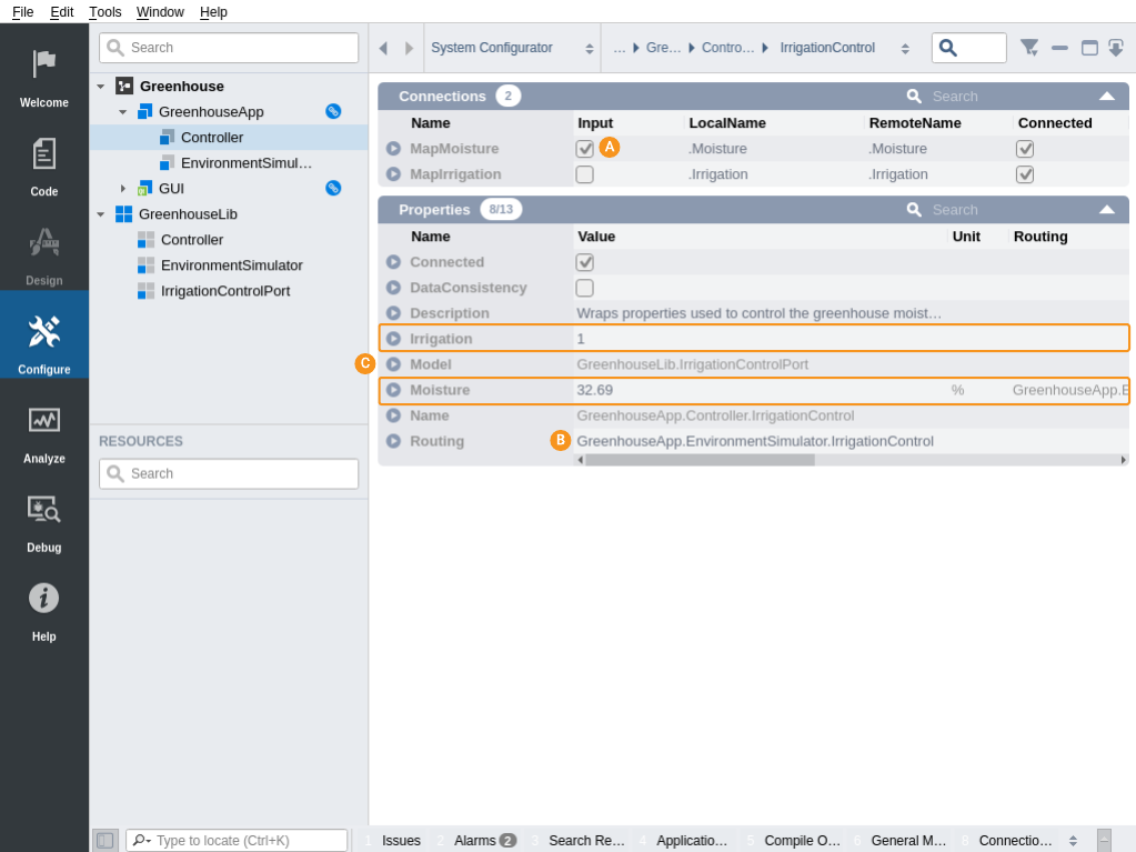
In this example, the Moisture is an input for the component and Irrigation is an output. The direction of the properties is set in Configure mode in the port Connections table () while the remote node the port is plugged to is set by the Routing property (). The connected nodes () appear as regular properties in Configure mode. In this example the Controller component is the one where routing has to be set for the Connections table to be valid for the Controller. Also the Controller component is the one controlling something so the port should be on the output side of the Controller. To achieve this two Properties are set on the IrrigationControl port in Controller model via model editor. The changes: TypeHint="RoutingType" and RoutingType="Push" - are visible in IrrigationControl properties table when Hide Base Model Items filter is disabled.
Replacing Simulation with Hardware
In the example project the IrrigationControlPort connects to another IrrigationControlPort. However, actually the other side does not need to be of same type. The port is able to connect to any node which has values named Moisture and Irrigation. This is useful because one way to replace EnvironmentSimulator component with actual hardware is to add an IOServer (e.g. Protocols - UDP I/O, Protocols - CANOpen I/O, Protocols - Modbus I/O, Protocols - I2C I/O etc.) which would either have signal channels named Moisture and Irrigation or for more complicated structures one can modify the RemoteName in the port's Connections table. The RemoteName properties can even be relative routings into different packets/nodes/devices of the IOServer. See CDPPort manual for more information.
Get started with CDP Studio today
Let us help you take your great ideas and turn them into the products your customer will love.