Modbus Configuration Manual
Introduction
The Modbus I/O Servers are CDPComponents that transform CDP values to and from the format required by the MODBUS protocol specification.
Click here for a quick guide how to set up a Modbus TCP Master/Slave Demo
Modbus Protocol Quick Guide
Modbus is a request/reply protocol where there typically is one client (Modbus master) and one or more servers (Modbus slaves). As the Modbus protocol initially was used on a shared line serial bus, each Modbus slave has a unique address (slave ID) on the bus. Valid slave IDs for a Modbus slave are 1 to 247. The Modbus master sends a request to the Modbus slave(s). The Modbus slave(s) that match the slave ID in the request will then process the request and return a reply. The Modbus master then processes the response from the Modbus slave.
There are several types of requests a Modbus master can issue. Each request contain a FunctionCode that tell the Modbus slave(s) what to do. The following FunctionCodes are supported by CDP Studio:
| Name of Function Code | Number | Description |
|---|---|---|
| ReadCoils | 0x01 / 01 | The Modbus master requests the slave to return a range of coil (digital) values. This FunctionCode can be used if the packet contains only physical digital input data |
| ReadDiscreteInputs | 0x02 / 02 | The same as ReadCoils, but FunctionCode is 2. |
| ReadHoldingRegisters | 0x03 / 03 | The Modbus master requests the Modbus slave to return a range of register values. This FunctionCode can be used if the packet contains only physical input data. |
| ReadInputRegisters | 0x04 / 04 | The same as ReadHoldingRegisters, except the functioncode is 4. |
| WriteMultipleCoils | 0x0f / 15 | The Modbus master requests the Modbus slave to write a supplied range of coil (digital) values to the specified register range. This FunctionCode can be used if the packet contains only physical digital output data. |
| WriteMultipleRegisters | 0x10 / 16 | The Modbus master requests the Modbus slave to write a supplied range of register values to the specified register range. This FunctionCode can be used if the packet contains only physical output data. |
| ReadWriteMultipleRegisters | 0x17 / 23 | The Modbus master asks the Modbus slave(s) to write an amount of data to registers starting at specified address, and to return a specified range of register values. This FunctionCode can be used if the packet contains both physical input and output data. |
Typical function codes used are ReadWriteMultipleRegisters, ReadHoldingRegisters and WriteMultipleRegisters. The other functioncodes are there to provide compatibility with old devices.
Note: The FunctionCode must be selected according to the data in the packet. For instance, FunctionCode ReadWriteMultipleRegisters can only be used if there is both input and output data in the packet. For only physical inputs, use ReadHoldingRegisters, and for only physical outputs, use WriteMultipleRegisters.
CDP Studio does not do any mapping of ReadAddress or WriteAddress according to the functioncode. (f.i. the ReadHoldingRegisters function code can be used with any Modbus address). It is the user's responsibility to set up the Read and Write addresses correctly.
The Modbus packets contain 16-bit register data values in a continuous array. The Modbus master specifies the start address where the Modbus slave should read or write (all) this data. If there are values that should not be read or written, these value addresses should not be within the range of the Modbus request. It is therefore important how the data is organized in the Modbus slave. To avoid having many packets, Modbus slave data that should be read and written should be organized in separate continuous arrays.
The Modbus addresses as defined by the modbus Standard are 16 bit, and thus range from 0 to 65535. Some manufacturers add a number in front of the Modbus address to signify that the address is analog or digital, input or output, or it may have some other manufacturer-defined meaning. This prefix number is not part of the modbus address, and must be removed when the modbus address is specified. To further complicate the issue, some manufacturers specify adresses as 1-based instead of 0-based. CDP Studio uses 0-based Modbus addresses.
Note: Be aware of how the Modbus slave has defined its modbus addresses, as it might be off by one, depending on the implementation.
By using CDP Studio you can easily map CDPSignal values into or out of the Modbus packets by using Routing. Each packet contains one or more consecutive IOModules (groupings) that hold a user-defined amount of CDPSignalChannels. The data from each channel is mapped into the packet address at the position where the channel is placed.
The table below shows the Modbus address layout of an example Modbus packet that starts at ReadAddress 0x00, and contains the CDPSignalChannels 'Speed', 'Position' and 'Acceleration':
| Modbus Address (Hex / Dec) | Name | Type | Data size (Modbus registers / bytes / bits) |
|---|---|---|---|
| 0x00 / 0 | Speed | CDPSignalChannel<unsigned short> | 1 Modbus register = 2 bytes = 16 bits |
| 0x01 / 1 | Position | CDPSignalChannel<unsigned int> | 2 Modbus registers = 4 bytes = 32 bits |
| 0x03 / 3 | Acceleration | CDPSignalChannel<short> | 1 Modbus register = 2 bytes = 16 bits |
The Packet address starts at 0x00, so this is where the first item 'Speed' maps into. It takes up one Modbus register in size, so the next data 'Position' is put at Modbus address 0x01. The 'Position' data takes up 2 Modbus registers in size. This means that the 'Acceleration' data is located at Modbus address 0x03. The total amount of data in the packet is 4 modbus registers, which is 8 bytes. As can be seen from the table, each item's size impacts the address of the next item. The Modbus packet maps the Modbus data array into (or out of) the CDPSignalChannels in the order and sizes that are specified.
Modbus in CDP Studio
The Modbus protocol is implemented in the following base I/O-servers:
| Name | Description |
|---|---|
| ModbusMasterUDP | A Modbus master that sends Modbus/TCP requests to a slave using the UDP network protocol. |
| ModbusMasterTCP | A Modbus master that sends Modbus/TCP requests to a slave using the TCP network protocol. |
| ModbusMasterRTU | A Modbus master that sends Modbus/RTU requests to a slave using a serial bus protocol. |
| ModbusSlaveUDP | A Modbus slave that accepts Modbus/TCP requests from the UDP network protocol |
| ModbusSlaveTCP | A Modbus slave that accepts Modbus/TCP requests from the TCP network protocol |
| ModbusSlaveRTU | A Modbus slave that accepts Modbus/RTU requests from a serial bus protocol |
In addition, some pre-configured I/O-servers have been made, to simplify setting up Modbus communication with supported devices, see Pre-made ModbusIOServers below.
Principle of Operation
Every period (as defined by fs), the Modbus master will try to send packets that are marked ready to send, in the order they are defined. If a response for a packet is not received within the Transport Timeout (or packet ResponseTimeout, if configured), then that slave ID is marked as inactive and put at the end of a retry list together with a time for when to retry. See ExponentialBackoffTime for more information on the exponential backoff time calculation.
After sending all packets that are marked ready to send, the Modbus master will pick the first packet from the retry list which is at or later than the packet send Time, and try to send that. When ResponseTimeout is set to a sensible value in relation to the Modbus fs, this ensures that non-responding Modbus slaves will cause minimal disturbance for the other responsive Modbus slaves.
Note: All the packets are sent in the order they are configured in the ModbusIO Packets table, given that they have been flagged for sending.
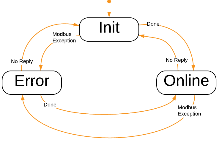
The Modbus master implements the internal states Init, Error and Online for handling of each Modbus slave ID as shown in the image below. The states correspond to the packet SendMode, except that state Online handles packets with SendMode Periodic, Trigger and OnChange:
A Modbus slave receives requests from a Modbus master. If the request matches a defined packet, then that response packet is returned to the Modbus master. If there is no matching Modbus slave ID, or there is a Broadcast request (slave ID 0) then no response is returned to the Modbus master.
States and Status
The Modbus I/O has the following states, as represented by the CurrentState property:
| State | Description |
|---|---|
| Offline | Indicates broken communication with all nodes (packets). Communication is still attempted, but as long as no nodes are online, the IOServer will be in Offline State. |
| Online | Indicates successful communication with one or more nodes (packets). The packet state can be retrieved from the packet's Online status. |
The signals NumberOfNodes and NumberOfNodesOnline can be used to tell how many packets are configured, and how many nodes are online.
Each packet also has an Online Property that is continously updated.
When the Modbus IO goes Offline, the Transmission Error alarm is set, indicating a failure. See CDPAlarm for more information on how to control Alarms.
Note: All this information can be used by other components in the system, to enable or disable system functionality. The relevant information can be Routed, or queried through a CDPConnector or CDPPort.
Transport Configuration
The Transport must be configured to tell the IOServer how to send and receive the data. The available transports are:
The Transport has a configurable Timeout (in seconds, f.i. '0.5'). This is the allowed amount of time to pass from a packet being sent until an answer is received (unless overridden by ResponseTimeout, see below).
Periodic packets are sent at the configured frequency (CDPComponent fs).
Note: In the event that no response is received within a Process Period, UDP and Serial will refresh the packet data and send the packet again, while TCP will resend the last packet without refreshing its data.
Pre-made ModbusIOServers
Some pre-made ModbusIOServers are provided. These are pre-set up to simplify configuration of the device, and typically have an IO packet and maybe some watchdog initialization packets. To function correctly, these IOServers usually only need the transport set up correctly, and some modules (that match the physical configuration) added to them. If the IOServer already has an IO packet, put your IOModules in there. See the models for the Weidmüller-UR20-FBC-MOD for an example of this.
Generic Modbus Configuration
The Modbus I/O Servers send the requests to slaves (numbered nodes) in the form of Modbus Packets.
First, select a suitable Modbus I/O server to use (see table above), either master or slave, TCP, UDP or RTU. Choose one of the pre-configured I/O servers if available for your target node; it simplifies the setup. Then set it up:
- The fs property determines the Send-rate for a Modbus master.
- The transport layer configuration must be set up in the Transport table. This can be either UDP, TCP or Serial. Take care to set a sensible Timeout as explained above.
- Packet(s) must be added into the Packets table and configured. See the table below for configuration options.
- Modules must be added to a packet to determine what data to read or write. A module is a logical grouping of CDPSignalChannels that encapsulates data to send or receive.
If there is no pre-configured I/O server available for your Node, the following properties must also be set:
- Set DigitalModuleHandling, see table below for more information.
- Set DigitalRegistersAreLinear, see table below for more information.
- Set ModuleOrdering, it is typically set to AsConfigured, see table below.
- Set NetworkConvert according to the node specification.
A Modbus slave packet has the following settings:
| Property Name | Description |
|---|---|
| Name | Unique packet name |
| SlaveID | The unique Modbus slave identifier |
| ReadAddress | The address that the first input channel uses. The following input channels get their data from the following addresses. |
| WriteAddress | The address that the first output channel uses. The following output channels write their data to the following addresses. |
| FunctionCode | How to transmit the data in the packet: If the data is read only, use ReadHoldingRegisters. Channels in the packet must have Input="0". If the data is write only, use WriteMultipleRegisters. Channels in the packet must have Input="1". If the data is read and write, use ReadWriteMultipleRegisters. Channels that have Input="0" will receive the 'Read' part, and Channels that have Input="1" will be sent to the connected node. |
| DigitalRegistersAreLinear | When this is 1, the digital registers are transfered 'Most Significant Byte' first. This is typically set for devices where digital channels are linear, but the analog channels are byteswapped (In other words; NetworkConvert is 1, but not for digital content registers). If DigitalRegistersAreLinear is set to 0, then the NetworkConvert property decides how to transfer the bytes in the Packet. |
| DigitalModuleHandling | Sets how to handle digital channels in memory.
|
| ModuleOrdering | Sets how to handle module ordering organization in memory.
|
| NetworkConvert | When checked, data will byteswapped (this can also be controlled on a per-channel level). |
| Online | When packet data is being communicated correctly (responses are received within the transport Timeout), then the packet is Online (1). If not, it is Offline(0). |
| Enable | Set to 1 to enable the packet. When Enable is 0, the packet is skipped. |
| LastSendTime | Last time this packet was sent. Time is number of seconds since epoch, as returned by CDPTime::GlobalClockMs(). It can be converted to human-readable time using the Automation::DecomposeTimestampOperator. |
| LastReceiveTime | Last time this packet received a reply. Time is number of seconds since epoch, as returned by CDPTime::GlobalClockMs(). It can be converted to human-readable time using the Automation::DecomposeTimestampOperator. |
| LastFailTime | Last time this packet had a failure. Time is number of seconds since epoch, as returned by CDPTime::GlobalClockMs(). It can be converted to human-readable time using the Automation::DecomposeTimestampOperator. |
| WaitTimeBetweenPackets | A configurable time (in seconds) to wait before sending. On a Modbus master the wait happens before sending the request, and on a Modbus slave the wait happens before sending the reponse. For Modbus RTU, this time is added to the '3.5 character times' inter-frame delay. |
| LastExceptionCode | Modbus Exception code as related to this packet. Typical values are 0 (no error), 1 (Illegal Function), 2 (Illegal Data Address), 3 (Illegal Data Value) and 4 (Slave Device Failure). |
A Modbus master packet has the following additional properties:
| Property Name | Description |
|---|---|
| RetryCount | When no response has been received from a request, this is the number of times to retry sending the packet before setting the packet Online property to 0. Note that for TCP transports, RetryCount is unused, as the connection will be closed and reopened when transport errors occur. |
| SendMode | How to send the data:
Note that packets which are ready to send are sent on the next run as specified by the fs property. |
| Trigger | Only valid when SendMode is 'Trigger'. Change from 0 to 1 to trigger sending the packet. |
| InitialFault | When set to 1, the master-packet has a fault condition before it is sent first time. Faulty packets trigger the IOServer Transmission Error alarm |
| CurrentRetry | When retrying send, this is the current retry number, limited by the packet RetryCount. If not retrying send, this number is 0. |
| PacketsLost | Total number of packets lost. This variable is incremented each time a Response is missing from a Request. Note that this number wraps around if it becomes larger than what the storage-type can handle. |
| PacketsSent | Total number of packets sent. This is incremented when a packet is sent. Note that this number wraps around if it becomes larger than what the storage-type can handle. |
| PacketsReceived | Total number of packets received. This is incremented when a packet is received. Note that this number wraps around if it becomes larger than what the storage-type can handle. |
| ResponseTimeout | The time (in seconds) to wait for a response; for instance 0.2. If ResponseTimeout is 0, then the Transport Timeout is used as ResponseTimeout. The ResponseTimeout is usually set to lessen the impact of a non-responding SlaveID (typically when using Modbus RTU), in conjunction with setting ExponentialBackoffTime. |
| ExponentialBackoffTime | The time (in seconds) used in the calculation for exponential backoff when no response is returned for a packet: Time-offset to next send for the packet = ExponentialBackoffTime*slaveID_send_try*slaveID_send_try. If ExponentialBackoffTime is 1 second and no reply is received for a packet then the next send time calculations for a packet for that SlaveID are as shown in the table ExponentialBackoffTime Timings. |
ExponentialBackoffTime Timings
| Send-try# | ExponentialBackoffTime | Calculation | Time-offset for next packet-send |
|---|---|---|---|
| 1 | 1 | 1*1*1 | 1 second |
| 2 | 1 | 1*2*2 | 4 seconds |
| 3 | 1 | 1*3*3 | 9 seconds |
| 4 | 1 | 1*3*3 | 9 seconds |
| ... | 1 | 1*3*3 | 9 seconds |
Note: As can be seen from the table above, the send-tries are limited to 3. See Principle of Operation for how the Modbus master implementation works.
Modules in Packets
A Modbus packet in CDP Studio contains one or more modules. Modules are named groupings of channels, and typically used to reflect a physical I/O module. Many hardware-manufacturers have stackable modules that can be put on their 'buscouplers' to add physical conversion to and from physical signals.
To enable easy configuration of these, the concept is mirrored in CDP Studio.
A Modbus I/O Module has the following properties, most of which are there to handle module/data-packing quirks:
| Property Name | Description |
|---|---|
| Name | The name of the module |
| InputBytesReservedBefore | The number of bytes to reserve before the actual input data in this module. Set this to the number of 'gap' bytes in front of the input data in this module (Typically set to 0). |
| OutputBytesReservedBefore | The number of bytes to reserve before the actual output data in this module. Set this to the number of 'gap' bytes in front of the output data in this module (Typically set to 0). |
| InputBytesReservedAfter | The number of bytes to reserve after the actual input data in this module. Set this to the number of 'gap' bytes after the input data in this module (Typically set to 0). |
| OutputBytesReservedAfter | The number of bytes to reserve after the actual output data in this module. Set this to the number of 'gap' bytes after of the output data in this module (Typically set to 0). |
Channels in Modules
Depending on the FunctionCode used, a Modbus master writes channels that have Input="1", and it reads channels that have Input="0". A Modbus slave handles write requests into channels that have Input="0", and it handles read requests from channels that have Input="1". This means that for a Modbus slave to mirror a Modbus master, then the setup of the Modbus master and Modbus slave is equal for the Packet setup (For instance, the Modbus slave has the same FunctionCode as the Modbus master). Note that the channels differ, in that the Input attribute on the Modbus master and Modbus slave is inverted (A Modbus slave has Input="1" and a Modbus master has Input="0" for the corresponding channel). See Modbus slave setup for more information.
Boolean (digital) channels are bit-packed into 16-bit Modbus registers so that the first channel becomes bit 0, the next is bit 1 and so on. Bitpacking per module is done according to the configuration of DigitalModuleHandling. Digital channels from adjacent modules are put together according to the ModuleOrdering configuration.
Large Data-types
The Modbus standard does not specify how to transfer data larger than 16 bits. This poses a challenge when working on data-types larger than 16 bits, as the byte-sequence of that data is not properly defined. The CDP Automation add-on defines a ByteSwap operator which can be used to manipulate the byte order of a signal.
In Modbus, int, {unsigned int},float, double and other large datatypes might require a ByteSwap operator on that signal to be converted corrrectly, depending on the implementation in the device being communicated with. For instance, the byte-sequence of float data '0123', where 0,1,2 and 3 represent bytes in the float, could be converted to '2301'. As devices have different implementations of the byteswapping of large data-types, it is advisable to test that the values sent match the values received. We recommend using a 'Hex to float' converter to test this. By generating a known number on one side, it is possible to test that the other side converts this correctly, and if not, use the 'Hex to float' converter to determine how the swapping becomes incorrect.
For instance, the hex value '0x1122331f' corresponds to the float value '1.27953e-28'. '11' fills one byte, '22' fills the next byte, '33' fills the third byte, and '1f' fills the last byte. (Note that the last byte can not be '44' due to restrictions in the IEEE 754 floating-point format). Send the value '1.27953e-28' from the transmitting side, and check the hex value that is received in a 'float to hex' converter. By looking at the byte positions of '11', '22', '33' and '1f' in the received hexadecimal number, it should be possible to determine how the ByteSwap operator should be configured to produce the correct result.
See ByteSwap operator for more information about the ByteSwap operator.
I/O Channel Scaling
Physical analog I/O modules typically accept 2-byte (short) values from the control-system. To see how these values map to physical values, please consult the manufacturer documentation for the module in question.
Let's say you are controlling a +/- 10 Volt output. In CDP, your program code is working with the values -1 to 1, since it is convenient to decouple the external details from your code. By looking up the manufacturer documentation for the Analog Output module, you learn that the module will output -10 Volt when it receives the value -32768, and that +10 Volt is output when the module receives a value of 32767. Values inbetween scale linearily between -32768 and 32767.
We can add a ScalingOperator to the output channel that scales the value '-1' to '-32768' and the value '1' to '32767':
| Name | InValue | OutValue |
|---|---|---|
| SP0 | -1 | -32768 |
| SP1 | 0 | 0 |
| SP2 | 1 | 32767 |
The above scaling-operator scales an input of -1 to -32768 , 0 is 0 and 1 is scaled to 32767. See the ScalingOperator for more information about how the scaling is done and how it works.
Watchdog
Some Modbus slave nodes have a watchdog function. A watchdog is typically a counter that counts down at a determined time-interval. If the watchdog is allowed to reach 0, the physical outputs of the node are set to a pre-defined value (typically 0, or last value). Whenever a Modbus access is performed, the watchdog is reloaded, preventing a timeout. This mechanism can help ensure that when communication to the physical equipment is lost, the equipment stops safely. Note that for problem-free operation, the Modbus master must be configured to send packets fast enough so that this watchdog in the Modbus slave is reloaded before it times out.
Value Change on Error
When a Modbus Packet goes to Offline state, the default behavior is to keep the last value for all physical input channels. It is the Packet Argument KeepLastValueOnDisconnect that controls this behavior:
- When it is set to 1 and the packet goes Offline, the packet keeps its physical input values to its last value.
- When it is set to 0 and the packet goes Offline, the physical inputs in the packet are forced to 0.
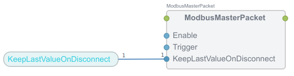
All packet KeepLastValueOnDisconnect Arguments are by default Routed to the governing KeepLastValueOnDisconnect property that is present in the ModbusIO component:
To change the default behavior so that all packet physical inputs get value 0 when the packet(s) go Offline, change the ModbusIO KeepLastValueOnDisconnect property to 0.
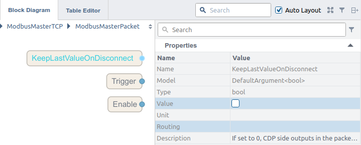
If you only want to change an individual packet's behavior so that it sets its physical inputs to 0 when it goes Offline, remove the Routing in the KeepLastValueOnDisconnect Argument for that packet, and set the Argument Value to 0:
See also the related topic Safe Value CDPSignals.
Modbus Slave Setup
The Modbus slave is set up from the perspective of the Modbus master. If the Modbus master has a packet with 'ReadHoldingRegisters', then the slave should also be set up with a packet with 'ReadHoldingRegisters'. The only difference is in the channels. For a Modbus master packet where the channels are set up with Input='0', the channels in the Modbus slave are set up with Input='1'. Where Modbus master channels have Input='1', the Modbus slave channels have Input='0'. In other words, set up the Modbus slave packet exactly as you would set up the Modbus master packet, but make sure to invert the Input in the Modbus slave channels relative to the Modbus master channels.
Note: If you have a Modbus master already set up, go into the Packet and copy all modules. Go into the corresponding Modbus slave packet and paste in the modules. Then go into each module in the Modbus slave and invert the Input attribute for all the channels in each module.
Debug Information
Various levels of Debug information can be enabled by setting the Debug property. When Debug = 0, only startup-errors are printed. If you encounter problems with Modbus communication, try increasing Debug to get more information about the cause of the failure. Increasing Debug increases the amount of information printed.
If Debug is set to 1, it will print out the configuration during Configure():
14:38:15.192 BRApp.BRIO: Configuring packet 'AIO' : FunctionCode='ReadWriteMultipleRegisters', SendMode='Periodic',
  DigitalModuleHandling='AlignOnByteBoundaryStrict', ModuleOrdering='AsConfigured', SlaveId=1,
  ReadAddress=0x0, WriteAddress=0x800, NetworkConvert='1', RetryCount='0', WaitTimeBeforeSend='0',
  ResponseTimeout='0.000000', ExponentialBackoffTime='0.000000'
14:38:15.196 CDPSignal[BRApp.BRIO.AIO.X20PS9400.BusSupplyCurrent]: Created CDPOperator DivOperator.
14:38:15.198 CDPSignal[BRApp.BRIO.AIO.X20PS9400.BusSupplyVoltage]: Created CDPOperator DivOperator.
14:38:15.198 BRApp.BRIO: Module='X20PS9400', #AI=0, #AO=3, #DI=0, #DO=0', ReadLength=6.00, WriteLength=0.00
14:38:15.201 BRApp.BRIO: Module='AO4-X20AO4632', #AI=4, #AO=0, #DI=0, #DO=0', ReadLength=0.00, WriteLength=8.00
14:38:15.204 BRApp.BRIO: Module='AI4-X20AI4222', #AI=0, #AO=4, #DI=0, #DO=0', ReadLength=8.00, WriteLength=0.00
14:38:15.210 BRApp.BRIO: Module='AI8-X20AI8321', #AI=0, #AO=8, #DI=0, #DO=0', ReadLength=16.00, WriteLength=0.00
14:38:15.212 BRApp.BRIO: Module='AO2-X20AO2437', #AI=2, #AO=2, #DI=0, #DO=0', ReadLength=4.00, WriteLength=4.00
14:38:15.213 BRApp.BRIO: packet 'AIO' : ReadLength=34, WriteLength=12'
When running periodically and Debug is set to 1, connection info and packet-sending will be printed:
14:38:16.654 BRApp.BRIO: Trying to send Periodic-packet 'BRApp.BRIO.AIO'
14:38:16.655 BRApp.BRIO: Trying to send Periodic-packet 'BRApp.BRIO.DIO'
14:38:16.656 BRApp.BRIO: Communication established.
14:38:16.754 BRApp.BRIO: Transport connected.
14:38:16.754 BRApp.BRIO: Trying to send Periodic-packet 'BRApp.BRIO.AIO'
14:38:16.755 BRApp.BRIO: Trying to send Periodic-packet 'BRApp.BRIO.DIO'
14:38:16.855 BRApp.BRIO: Trying to send Periodic-packet 'BRApp.BRIO.AIO'
14:38:16.855 BRApp.BRIO: Trying to send Periodic-packet 'BRApp.BRIO.DIO'
When running periodically and Debug is set to 2, the packet data sent and received will be printed in addition:
14:38:17.457 BRApp.BRIO: Trying to send Periodic-packet 'BRApp.BRIO.AIO'
14:38:17.457 BRApp.BRIO.AIO: SendRequest: 10 81 00 00 00 17 01 17 00 00 00 11 08 00 00 06 0c 00 00 00 00 00 00 00 00 00 00 00 00
14:38:17.458 BRApp.BRIO.AIO: ReadResponse: 10 81 00 00 00 25 01 17 22 00 00 00 03 00 36 ff fe 7f ff 7f ff 7f ff 19 99 00 00 00 00 00 04 00 01 00 01 00 00 00 00 00 00 00 04
14:38:17.458 BRApp.BRIO: Setting state 'Online' for Modbus slave ID 1
To determine errors in module configurations, Debug can be set to 3. The Modbus IO will then print at which byte offset it maps the various channels into. This information can be used together with knowledge about the I/O layout to determine if something is set up wrong.
14:43:20.311 BRApp.Wago-750-UDP: Configuring packet 'IO' : FunctionCode='ReadWriteMultipleRegisters', SendMode='Periodic',
  DigitalModuleHandling='AlignAdjacent', ModuleOrdering='AnalogFirst', SlaveId=1,
  ReadAddress=0x0, WriteAddress=0x0, NetworkConvert='1', RetryCount='0', WaitTimeBeforeSend='0',
  ResponseTimeout='0.000000', ExponentialBackoffTime='0.000000'
14:43:20.317 BRApp.Wago-750-UDP: Module='750-431', #AI=0, #AO=0, #DI=0, #DO=8', ReadLength=1.00, WriteLength=0.00
14:43:20.324 BRApp.Wago-750-UDP: Module='750-530', #AI=0, #AO=0, #DI=8, #DO=0', ReadLength=0.00, WriteLength=1.00
14:43:20.329 BRApp.Wago-750-UDP: Module='750-451', #AI=0, #AO=8, #DI=0, #DO=0', ReadLength=16.00, WriteLength=0.00
14:43:20.341 BRApp.Wago-750-UDP: Module='750-1406', #AI=0, #AO=0, #DI=0, #DO=16', ReadLength=2.00, WriteLength=0.00
14:43:20.341 BRApp.Wago-750-UDP: IO.750-451.AI0 Byte Offset [AI: 0]
14:43:20.341 BRApp.Wago-750-UDP: IO.750-451.AI1 Byte Offset [AI: 2]
14:43:20.341 BRApp.Wago-750-UDP: IO.750-451.AI2 Byte Offset [AI: 4]
14:43:20.341 BRApp.Wago-750-UDP: IO.750-451.AI3 Byte Offset [AI: 6]
14:43:20.341 BRApp.Wago-750-UDP: IO.750-451.AI4 Byte Offset [AI: 8]
14:43:20.341 BRApp.Wago-750-UDP: IO.750-451.AI5 Byte Offset [AI: 10]
14:43:20.341 BRApp.Wago-750-UDP: IO.750-451.AI6 Byte Offset [AI: 12]
14:43:20.341 BRApp.Wago-750-UDP: IO.750-451.AI7 Byte Offset [AI: 14]
14:43:20.341 BRApp.Wago-750-UDP: IO.750-431.DI0 Byte Offset [DI: 17]
14:43:20.341 BRApp.Wago-750-UDP: IO.750-431.DI1 Byte Offset [DI: 17]
14:43:20.341 BRApp.Wago-750-UDP: IO.750-431.DI2 Byte Offset [DI: 17]
14:43:20.341 BRApp.Wago-750-UDP: IO.750-431.DI3 Byte Offset [DI: 17]
14:43:20.341 BRApp.Wago-750-UDP: IO.750-431.DI4 Byte Offset [DI: 17]
14:43:20.341 BRApp.Wago-750-UDP: IO.750-431.DI5 Byte Offset [DI: 17]
14:43:20.341 BRApp.Wago-750-UDP: IO.750-431.DI6 Byte Offset [DI: 17]
14:43:20.341 BRApp.Wago-750-UDP: IO.750-431.DI7 Byte Offset [DI: 17]
14:43:20.341 BRApp.Wago-750-UDP: IO.750-530.DO0 Byte Offset [DO: 1]
14:43:20.341 BRApp.Wago-750-UDP: IO.750-530.DO1 Byte Offset [DO: 1]
14:43:20.341 BRApp.Wago-750-UDP: IO.750-530.DO2 Byte Offset [DO: 1]
14:43:20.341 BRApp.Wago-750-UDP: IO.750-530.DO3 Byte Offset [DO: 1]
14:43:20.341 BRApp.Wago-750-UDP: IO.750-530.DO4 Byte Offset [DO: 1]
14:43:20.341 BRApp.Wago-750-UDP: IO.750-530.DO5 Byte Offset [DO: 1]
14:43:20.341 BRApp.Wago-750-UDP: IO.750-530.DO6 Byte Offset [DO: 1]
14:43:20.341 BRApp.Wago-750-UDP: IO.750-530.DO7 Byte Offset [DO: 1]
14:43:20.341 BRApp.Wago-750-UDP: IO.750-1406.DI00       Byte Offset [DI: 16]
14:43:20.341 BRApp.Wago-750-UDP: IO.750-1406.DI01       Byte Offset [DI: 16]
14:43:20.341 BRApp.Wago-750-UDP: IO.750-1406.DI02       Byte Offset [DI: 16]
14:43:20.341 BRApp.Wago-750-UDP: IO.750-1406.DI03       Byte Offset [DI: 16]
14:43:20.341 BRApp.Wago-750-UDP: IO.750-1406.DI04       Byte Offset [DI: 16]
14:43:20.341 BRApp.Wago-750-UDP: IO.750-1406.DI05       Byte Offset [DI: 16]
14:43:20.341 BRApp.Wago-750-UDP: IO.750-1406.DI06       Byte Offset [DI: 16]
14:43:20.341 BRApp.Wago-750-UDP: IO.750-1406.DI07       Byte Offset [DI: 16]
14:43:20.341 BRApp.Wago-750-UDP: IO.750-1406.DI08       Byte Offset [DI: 19]
14:43:20.341 BRApp.Wago-750-UDP: IO.750-1406.DI09       Byte Offset [DI: 19]
14:43:20.341 BRApp.Wago-750-UDP: IO.750-1406.DI10       Byte Offset [DI: 19]
14:43:20.341 BRApp.Wago-750-UDP: IO.750-1406.DI11       Byte Offset [DI: 19]
14:43:20.341 BRApp.Wago-750-UDP: IO.750-1406.DI12       Byte Offset [DI: 19]
14:43:20.341 BRApp.Wago-750-UDP: IO.750-1406.DI13       Byte Offset [DI: 19]
14:43:20.341 BRApp.Wago-750-UDP: IO.750-1406.DI14       Byte Offset [DI: 19]
14:43:20.341 BRApp.Wago-750-UDP: IO.750-1406.DI15       Byte Offset [DI: 19]
14:43:20.341 BRApp.Wago-750-UDP: packet 'IO' : ReadLength=20, WriteLength=2'
Modbus TCP Master / Slave Demo
Modbus TCP Master / Slave Demo - Describes how to run and configure a ModbusMaster and slave TCP Demo
Get started with CDP Studio today
Let us help you take your great ideas and turn them into the products your customer will love.