B&R Automation Setup Guide
Introduction
This guide demonstrates a system that uses a 'B&R-X20-BC-0087' Modbus Master to transfer analog and digital values to and from a 'B&R X20 BC 0087' bus coupler with CDP Studio, the independent automation software for open PC-based real-time distributed control systems.
For communication with other bus couplers/devices, please see the Modbus Configuration Manual.
We will set up the modules so that values are looped from the physical outputs to the physical inputs.
Requirements: A 24-volt power supply unit (PSU), a network cable, and the following B&R equipment:
- X20 BC 0087 - bus coupler with IP address set to 192.168.100.1
- X20 PS 9400 - power module
- X20 AO 4632 - analog ouput
- X20 AI 4222 - analog input
- X20 DO 9322 - digital output
- X20 DI 9371 - digital input
Note: Make sure that the device has a default configuration, as detailed in the Default Configuration. Unless the I/O has a default module configuration, you will get issues because of a mismatch between the process image in Modbus I/O versus the process image in the B&R I/O.
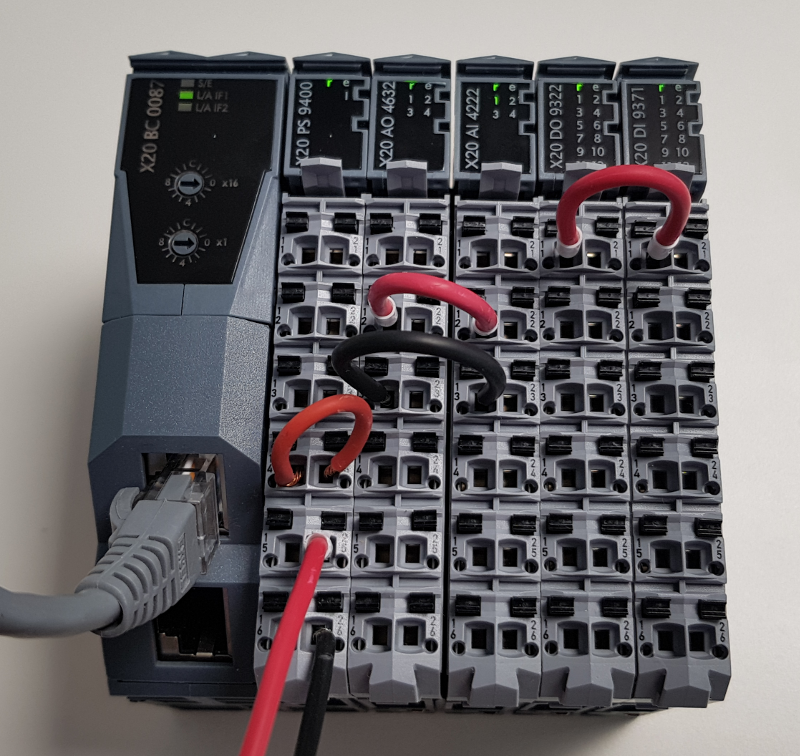
Assemble the physical X20 system by putting together all the modules and adding them in the order given in the list above.
Connect physical wires so that we loop the outputs to the inputs:
- Connect PS 9400.14 with PS 9400.24
- Connect AO 4632.12 with AI 4222.12
- Connect AO 4632.13 with AI 4222.13
- Connect DO 9322.11 with DI 9371.11
- Connect 24 Volts from PSU to PS 9400.25
- Connect 0 Volts from PSU to PS 9400.26
- You should end up with something like this:

Plug in the PSU and make sure that the bus coupler is connected via ethernet and reachable from the machine running CDP Studio. This may involve changing the IP address and network mask of an ethernet interface on the machine running CDP Studio to something like 192.168.100.10/24.
Set Up a Test System
First, we set up a System that the B&R I/O can be tested in:
Create a system named BRDemo with a Console application named BRDemoApp, then select Configure mode. See How to Create a system for more information.
Set up Modbus Master in the Application
- Select the BRDemoApp that resides under BRDemo in the Project tree
- In the Resource tree, expand the ModbusIO resource
- Right-click/add a BR-Automation-X20-BC-0087-UDP to BRDemoApp:
Note: You can also double-click on a resource to add it. Resources are always added as children to the currently selected item in the Project tree.
- Select the BR-Automation-X20-BC-0087-UDP that was added
- From the Resource tree, under 'B&R-AutomationIOModules', right-click/add a ModbusMasterPacketAnalog to the Packets section in the BR-Automation-X20-BC-0087-UDP
- In the 'Packets' table, rename the ModbusMasterPacketAnalog to AIO
- Double-click the AIO packet to go into it
- In the Properties table, edit the FunctionCode row of the AIO packet. Make sure it is set to ReadWriteMultipleRegisters to both send and retrieve data
- Set SlaveID to '1'
- In the following steps, we will add the modules X20PS9400, X20AO4632 and X20AI4222 to the configuration
- In Resource tree 'Search', type in 9400 to get a smaller selection to choose from
- In the Resource tree, double-click on X20PS9400 to add it
- In Resource tree 'Search', delete the previous text, type in 4632 to get a smaller selection to choose from
- In the Resource tree, double-click on X20AO4632 to add it
- In Resource tree 'Search', delete the previous text, and type in 422 to get a smaller selection to choose from
- In the Resource tree, double-click on X20AI4222 to add it
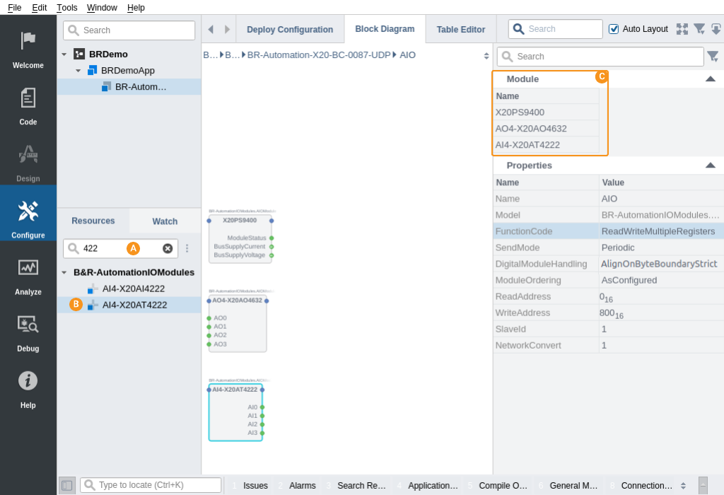
- The ordered Module configuration should now look like this:

- Click the BR-Automation-X20-BC-0087-UDP in the Project tree
- Clear the Resource tree search
- In the Resource tree, under 'B&R-AutomationIOModules', right-click/add a ModbusMasterPacketDigital to the Packets section in the BR-Automation-X20-BC-0087-UDP
- In the 'Packets' table, rename the ModbusMasterPacketDigital to DIO
- Double-click the DIO packet to go into it
- In the Properties table, edit the FunctionCode row of the DIO packet. Make sure it is set to ReadWriteMultipleRegisters to both send and retrieve data
- Set SlaveID to '1'
- In the following steps, we will add the modules X20DO9322 and X20DI9371 to the configuration
- In Resource tree 'Search', type in 9322 to get a smaller selection to choose from. If you do not see any modules, make sure that you added a ModbusMasterPacketDigital packet in a previous step
- In the Resource tree, double-click on X20DO9322 to add it
- In Resource tree 'Search', delete the previous text, and type in 9371 to get a smaller selection to choose from
- In the Resource tree, double-click on X20DI9371 to add it
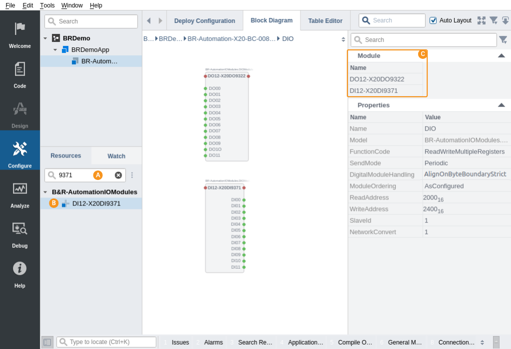
- The ordered Module configuration should look similar to this:

- You can adjust how often the data should be exchanged with the physical I/O by setting the fs property of the BR-Automation-X20-BC-0087-UDP. 10 Hz is enough for this simple demo. Be aware that you might also have to adjust the Watchdog timeout if you change the fs
Configure Where to Connect
We have now set up a Modbus master to communicate with the B&R X20 BC 0087. Now we must set up to where it should connect:
- Select the Deploy Configuration tab and look into the Networks table. For our test, the selected network should be a network where the B&R bus coupler IP address (192.168.100.1) is available at. Select the network that can reach this address in the Networks table
- Select the BR-Automation-X20-BC-0087-UDP component inside the BRDemoApp in the Project tree
- In the Transport table, make sure the RemoteIP of the target device is set to 192.168.100.1 (the IP address of the bus coupler)
How to Run the Tutorial
To run the tutorial from CDP Studio, select Configure mode, right-click on the system project and select Run & Connect. See the Running and Connecting to the System tutorial for more information.
Test the Communication
- Enter into BRDemoApp BR-Automation-X20-BC-0087-UDP AIO X20AO4632
- In AO0, Change the Value to 15000
- Enter into BRDemoApp BR-Automation-X20-BC-0087-UDP AIO X20AI4222
- Verify that AI0 has a value near 15000 (It will not be exact due to Analog/Digital conversion inaccuracies). If it does not match, go through this guide once more and verify each step
Note: The values for most analog I/O's are typically in the range -32768 to 32767. By adding a ScalingOperator<double> to the AO0 channel, and then adding ScalingPoints to the ScalingOperator, it is possible to scale the value so that -32768 corresponds with -10 volt, and 32767 corresponds to 10 volt, so that when you write -10 to the AO0, it would be scaled so that -32768 is what the physical module sees. Always check the vendor documentation to find the suitable scaling for each module. In a proper setup, you would typically set 'Routing' on AI0 so that it retrieves (from another signal in the system) the value to set on the I/O.
- Enter into BRDemoApp BR-Automation-X20-BC-0087-UDP DIO X20DO9322
- Click the DO0 check-box so that it is checked.
- Enter into BRDemoApp BR-Automation-X20-BC-0087-UDP DIO X20DI9371
- Verify that DI0 checkbox is checked
Note: You can set up additional packets to transfer other data than analog and digital I/O. See the vendor Modbus documentation for more information about this. Note that in the Modbus packet(s), you must set the correct FunctionCode according to inputs, outputs or both in the data in the packet. DigitalModuleHandling='AlignOnByteBoundary', ModuleOrdering='AsConfigured' and ReadAddress and WriteAddress must also be set correctly for communication with a B&R X20 module to work correctly.
Troubleshooting
The Application Output window contains messages from the application. 'Error' or 'Warning' messages found there indicate problems. The CurrentState property of 'BR-Automation-X20-BC-0087-UDP' should show 'Online'.
The BR-Automation-X20-BC-0087-UDP not going to the 'Online' state can typically be caused by:
- No power to the system, or a hardware fault in the system. Turn off the power, check all connections and turn the power on again if everything seems correct
- No connection between master and slave (IPAddress wrong, no route to host...)
- Modules are in the wrong order, or missing from the configuration, or too many modules are set up. Always make sure that the configuration matches the physical order of modules exactly. Only modules that don't affect the process image in the bus coupler can be omitted
- Incorrect Physical wiring of the modules could cause outputs to not set the correct values out
- The Master is Suspended due to some other issue
The NumberOfNodesOnline signal in the Modbus IOServer tells how many packets are actively used at any moment.
Note: More information about what is going on can be obtained by setting the IOServer Property Debug to '1' or '2'. Remember to set it back to 0 after finding the cause of the problem.
See also Protocols - Modbus I/O.
Get started with CDP Studio today
Let us help you take your great ideas and turn them into the products your customer will love.