Modbus Configuration Manual
Introduction
The Modbus I/O Servers are CDPComponents that convert CDP values to and from the Modbus protocol format. For more information about Modbus details, refer to the MODBUS protocol specification.
For a step-by-step setup guide on how to set up both a Modbus Master and a Modbus Slave, see the Modbus TCP Master and Modbus TCP Slave setup guide.
Usage
To implement Modbus communication in CDP Studio, determine the transport type (Serial, UDP, or TCP) and whether your device will act as a Modbus Master (client) or Modbus Slave (server). Choose the appropriate model from the ModbusIO resource.
Pre-configured Models
For devices with stackable modules (e.g., Wago, B&R, Weidmueller), select one of the pre-configured IOServer models, such as ModbusIO.Wago-750-UDP or Weidmueller-UR20-FBC-MOD-TCP. These models have pre-configured device settings and a pre-setup IO packet that allows you to add modules in physical order, simplifying the setup.
Note: Pre-configured models eliminate the need for manual setup by having pre-defined settings and packets based on the device's modules.
Generic Models
If your device does not have a pre-defined setup in CDP Studio, use the following models:
- ModbusIO.ModbusMasterTCP, ModbusIO.ModbusMasterUDP, ModbusIO.ModbusMasterRTU for Modbus masters (clients)
- ModbusIO.ModbusSlaveTCP, ModbusIO.ModbusSlaveUDP, ModbusIO.ModbusSlaveRTU for Modbus slaves (servers) (see Modbus Slave Setup below)
CDPTransport Models
Sometimes it is convenient to tunnel Modbus frames through another device or protocol. The ModbusIO.CDPTransport models use CDPTransport to carry data via the Messenger component. This makes it possible, for example, to forward Modbus traffic through an intermediate device (e.g., a WAGO 750-652) by connecting a CDPTransport endpoint to that device.
The following CDPTransport-based models are available:
| Model | Description |
|---|---|
| ModbusIO.ModbusMasterRTU_CDPTransport | A Modbus client (master) that transports Modbus/RTU frames |
| ModbusIO.ModbusMaster_CDPTransport | A Modbus client (master) that transports Modbus/TCP ADUs |
| ModbusIO.ModbusSlaveRTU_CDPTransport | A Modbus server (slave) that transports Modbus/RTU frames |
| ModbusIO.ModbusSlave_CDPTransport | A Modbus server (slave) that transports Modbus/TCP ADUs |
Note: Fragmentation through intermediates. Some devices may segment payloads internally. As a result, a single Modbus/RTU frame may arrive in multiple chunks.
When tunneling RTU:
- Treat CDPTransport/Messenger message boundaries as arbitrary—not equal to RTU frames.
- If possible, implement reassembly on the receiver: buffer bytes until a complete RTU frame is available, using the function-dependent length plus CRC16 validation and/or a 3.5-character inter-frame timeout heuristic.
- Test with the exact module configuration; larger internal buffers reduce the frequency of splits.
(Modbus/TCP can also be segmented by TCP, but the MBAP length field enables deterministic reassembly; buffer until the declared length is satisfied.)
Overview
Modbus I/O Servers organize data in packets, each containing a SlaveId, FunctionCode, ReadAddress, and WriteAddress. The packets contain IOModules, which contain the data represented by CDPSignalChannels. A packet can contain one or more IOModules that together make up the Modbus packet data.
Note: The Input attribute in CDPSignalChannels specifies whether the data is input (Input=1) or output (Input=0) for the Modbus device.
You need to know the address and size of the data for your Modbus device. Some devices may require multiple packets to handle all the necessary data. Always refer to the device’s datasheet to avoid mistakes.
Modbus Protocol Quick Guide
Modbus is a request/reply protocol with one client (Modbus master) and one or more servers (Modbus slaves). Each slave has a unique address (SlaveId). CDP Studio supports SlaveIds from 0 to 255, with SlaveId 0 reserved for broadcast requests when using Modbus/RTU.
In Modbus, each request contains a Slave ID (or Unit ID), and only the addressed slave is allowed to reply. When the master sends a broadcast request (Slave ID = 0), all slaves must execute the request but none may send a response. Only write-type function codes are valid for broadcast, since broadcasts cannot generate replies.
Modbus Requests and Function Codes
Each request from the Modbus master contains a FunctionCode, which instructs the slaves on what action to perform. CDP Studio supports the following FunctionCodes:
| Function Code Name | Number | Description |
|---|---|---|
| ReadCoils | 0x01 / 01 | Requests a range of coil (digital) values. |
| ReadDiscreteInputs | 0x02 / 02 | Similar to ReadCoils but for discrete inputs. |
| ReadHoldingRegisters | 0x03 / 03 | Requests a range of register values. |
| ReadInputRegisters | 0x04 / 04 | Similar to ReadHoldingRegisters but for input registers. |
| WriteMultipleCoils | 0x0f / 15 | Writes a range of coil (digital) values to registers. |
| WriteMultipleRegisters | 0x10 / 16 | Writes a range of register values to registers. |
| ReadWriteMultipleRegisters | 0x17 / 23 | Writes data to registers and returns register values. |
Data Handling
- Write requests are filled with values from Input=1 CDPSignalChannels.
- For Read requests, the Modbus response data is decoded into the Input=0 CDPSignalChannels.
- See ModuleOrdering, DigitalModuleHandling and DigitalRegistersAreLinear for special ordering options.
Commonly used FunctionCodes include ReadWriteMultipleRegisters, ReadHoldingRegisters, and WriteMultipleRegisters. Other FunctionCodes exist for compatibility with older devices.
Note: Select FunctionCode according to the data in the packet:
- Use ReadWriteMultipleRegisters when both input and output data shall be transferred.
- Use ReadHoldingRegisters to read data from the device into Input="0" CDPSignalChannels.
- Use WriteMultipleRegisters to write Input="1" CDPSignalChannels to the device.
- Whenever you add, remove, or modify modules, ensure that the FunctionCode for the corresponding packet is validated based on the criteria mentioned above.
Addressing
The Modbus master packet specifies the ReadAddress and/or WriteAddress for where the slave should begin reading or writing data. If certain addresses should not be accessed, split the data into multiple packets with different start-addresses.
Modbus addresses are 16-bit and range from 0 to 65535. Each address typically identifies a 16 bit value. Some manufacturers use 1-based addressing and/or add a prefix to signify address type. See the translation table below. CDP Studio uses 0-based addressing.
Note: CDP Studio does not map ReadAddress or WriteAddress based on FunctionCodes. You must specify the addresses correctly. Check how the Modbus slave defines its addresses, as some implementations may be off by one. Below is a translation table for Modicon and similar device addresses:
Modicon to CDP Studio Translation Table
Some vendors use '1', '3' and '4' prefixes to their Modbus address to signify both access type and address. These prefixes (0xxxx, 1xxxx, 3xxxx, 4xxxx) do not exist in the Modbus protocol. They are documentation conventions, not actual protocol addresses. The conversion to a CDP Studio modbus address is done by removing the prefix and subtracting 1 from the address, as shown in the table below:
| Modicon Device Address | Modbus Address | FunctionCode |
|---|---|---|
| 00001 to 09999 | 0 to 9998 | ReadCoils / WriteMultipleCoils |
| 10001 to 19999 | 0 to 9998 | ReadDiscreteInputs |
| 30001 to 39999 | 0 to 9998 | ReadInputRegisters |
| 40001 to 49999 | 0 to 9998 | ReadHoldingRegisters / WriteMultipleRegisters / ReadWriteMultipleRegisters |
Note: Reading or writing outside of a defined address and range will result in a Modbus exception response from the Modbus slave, meaning that the request is not handled. See LastExceptionCode for more information.
Transport Configuration
Configure the transport to determine how the IOServer sends and receives data. Supported transports include:
The Transport has a configurable Timeout in seconds (e.g., 0.5). This defines how long to wait for a response after sending a packet.
Note: Each Packet can override the transport Timeout by specifying ResponseTimeout.
Pre-made ModbusIOServers
Pre-made Modbus I/O Servers simplify device configuration. These models typically include an IO packet and (possibly watchdog) initialization packets, as well as advanced settings to make the modules map correctly into the modbus data packet. To configure these IOServers, set up the transport and add modules matching the physical configuration to the pre-defined packet(s).
Generic Modbus Configuration
To configure a generic Modbus I/O server:
- Set the fs property to define the periodic Send-rate of a Modbus master.
- Set the transport layer in the Transport table and define a sensible Timeout.
- Unless there are pre-made packets that can be used, add and configure packet(s) in the Packets table.
- Add IOModule(s) to packets to determine the data to read or write.
- Make sure the IOModules have CDPSignalChannels in correct order and size so that they 'map' into the modbus data packet.
If a pre-configured IOServer is not available, additional properties (e.g., DigitalModuleHandling, DigitalRegistersAreLinear, and ModuleOrdering) must be configured.
Debug Information
Set the Debug property to enable various levels of debug output to the Application log:
- 0 – Only startup errors are printed.
- 1 – Prints configuration details during Configure() and connection information during packet sends.
- 2 – Prints packet data sent and received.
- 3 – Prints byte offsets for mapped channels.
Watchdog
Some Modbus slaves have a watchdog function, which resets device outputs to a default state if communication is lost. When enabled, the Modbus master must send packets fast enough to prevent the watchdog from timing out.
Value Change on Error
When a Modbus Packet goes offline, it defaults to setting all physical input channels to 0. Use the KeepLastValueOnDisconnect argument to change this behavior:
- 1 – Retain the last values of physical inputs when the packet goes offline.
- 0 – Set physical inputs to 0 when the packet goes offline.
To change the default behavior for all packets, adjust the KeepLastValueOnDisconnect property in the ModbusIO component.
Principle of Operation
Every period (as defined by fs), the Modbus master will try to send packets that are marked ready to send, in the order they are defined. If a response for a packet is not received within the Transport Timeout (or packet ResponseTimeout, if configured), then that slave ID is marked as inactive and put at the end of a retry list together with a time for when to retry. See ExponentialBackoffTime for more information on the exponential backoff time calculation.
After sending all packets that are marked ready to send, the Modbus master will pick the first packet from the retry list which is at or later than the packet send Time, and try to send that. When ResponseTimeout is set to a sensible value in relation to the Modbus fs, this ensures that non-responding Modbus slaves will cause minimal disturbance for the other responsive Modbus slaves.
Note: All the packets are sent in the order they are configured in the ModbusIO Packets table, given that they have been flagged for sending.
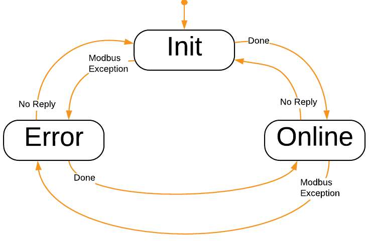
The Modbus master implements the internal states Init, Error and Online for handling of each Modbus SlaveId as shown in the image below. Each Modbus SlaveId has an internal communication state: Init, Error, or Online. These states reflect the result of actual communication, not the packet's SendMode.
A SlaveId enters the Online state only after the master has successfully sent a request and received a valid reply. If no valid response is received (timeout, CRC/MBAP mismatch, exception, or transport error), the SlaveId remains in Error or Init.
SendMode (Periodic, OnChange, Trigger, Init, Error) only determines when a packet is scheduled to be sent, not the communication state. Packets in any SendMode can only be considered "Online" when valid replies are received.
A Modbus slave receives requests from a Modbus master. If the request matches a defined packet, then that response packet is returned to the Modbus master. If there is no matching Modbus SlaveID, or there is a Broadcast request (slave ID 0 for Modbus/RTU) then no response is returned to the Modbus master.
States and Status
The Modbus I/O has the following states, as represented by the CurrentState property:
| State | Description |
|---|---|
| Offline | Indicates broken communication with all nodes (packets). Communication is still attempted, but as long as no nodes are online, the IOServer will be in Offline State. |
| Online | Indicates successful communication with one or more nodes (packets). The packet state can be retrieved from the packet's Online status. |
The signals NumberOfNodes and NumberOfNodesOnline can be used to tell how many packets are configured, and how many nodes are online.
Each packet also has an Online Property that is continuously updated based on the reception of data.
When the Modbus IO goes Offline, the Transmission Error alarm is set, indicating a failure. See CDPAlarm for more information on how to set up Alarms.
Note: All this information can be used by other components in the system, to enable or disable system functionality. The relevant information can be Routed, or queried through a CDPConnector or CDPPort.
Packets
Periodic packets are sent at the configured I/O server frequency (fs).
A Modbus slave packet has the following settings:
| Property Name | Description |
|---|---|
| Name | Unique packet name |
| SlaveID | The unique Modbus slave identifier (1-247 for RTU, 0-255 for TCP or UDP) |
| ReadAddress | The address that the first input channel uses. The following input channels get their data from the following addresses. |
| WriteAddress | The address that the first output channel uses. The following output channels write their data to the following addresses. |
| FunctionCode | How to transmit the data in the packet: If the data is read-only, use ReadHoldingRegisters. Channels in the packet must have Input="0". If the data is write-only, use WriteMultipleRegisters. Channels in the packet must have Input="1". If the data is read and write, use ReadWriteMultipleRegisters. Channels that have Input="0" will receive the 'Read' part, and Channels that have Input="1" will be sent to the connected device. |
| DigitalRegistersAreLinear | When this is 1, the digital registers are transferred 'Most Significant Byte' first. This is typically set for devices where digital channels are not byte-swapped, but the analog channels are byte-swapped. If DigitalRegistersAreLinear is set to 0, then the NetworkConvert property decides how to transfer the bytes in the Packet. |
| DigitalModuleHandling | Sets how to handle digital channels in memory.
|
| ModuleOrdering | Sets how to handle module ordering organization in memory.
|
| NetworkConvert | When checked, data in the packet will byte-swapped. |
| Online | When packet data is being communicated correctly (responses are received within the timeout), then the packet is Online (1). If not, it is Offline(0). |
| Enable | Set to 1 to enable the packet. When Enable is 0, the packet is skipped. |
| LastSendTime | Last time this packet was sent. Time is the number of seconds since epoch, as returned by CDPTime::GlobalClockMs(). It can be converted to human-readable time using the Automation::DecomposeTimestampOperator. |
| LastReceiveTime | Last time this packet received a reply. Time is the number of seconds since epoch, as returned by CDPTime::GlobalClockMs(). It can be converted to human-readable time using the Automation::DecomposeTimestampOperator. |
| LastFailTime | Last time this packet had a failure. Time is the number of seconds since epoch, as returned by CDPTime::GlobalClockMs(). It can be converted to human-readable time using the Automation::DecomposeTimestampOperator. |
| WaitTimeBetweenPackets | A configurable time (in seconds) to wait before sending. On a Modbus master, the wait happens before sending the request, and on a Modbus slave, the wait happens before sending the response. For Modbus RTU, this time is added to the '3.5 character times' inter-frame delay. |
| LastExceptionCode | Modbus Exception code as related to this packet. Typical values are 0 (no error), 1 (Illegal Function), 2 (Illegal Data Address), 3 (Illegal Data Value) and 4 (Slave Device Failure). A Modbus exception typically means that the request was received, but something was wrong with the packet such as address or amount of data causing access outside of the allowed area. |
A Modbus master packet has the following additional properties:
| Property Name | Description |
|---|---|
| RetryCount | When no response has been received from a request, this is the number of times to retry sending the packet before setting the packet Online property to 0. For TCP, RetryCount is not used because error recovery is handled at the connection level. |
| SendMode | How to send the data:
Note that packets that are ready to send are sent on the next run as specified by the fs property. |
| Trigger | Only valid when SendMode is 'Trigger'. Change from 0 to 1 to trigger sending the packet. |
| InitialFault | When set to 1, the master-packet has a fault condition before it is sent first time. Faulty packets trigger the IOServer Transmission Error alarm |
| CurrentRetry | When retrying send, this is the current retry number, limited by the packet RetryCount. If not retrying send, this number is 0. |
| PacketsLost | Total number of packets lost. This variable is incremented each time a Response is missing from a Request. Note that this number wraps around if it exceeds the maximum value that the storage type can handle. |
| PacketsSent | Total number of packets sent. This is incremented when a packet is sent. Note that this number wraps around if it exceeds the maximum value that the storage type can handle. |
| PacketsReceived | Total number of packets received. This is incremented when a packet is received. Note that this number wraps around if it exceeds the maximum value that the storage type can handle. |
| ResponseTimeout | The time (in seconds) to wait for a response; for instance 0.2. If ResponseTimeout is 0, then the Transport Timeout is used as ResponseTimeout. The ResponseTimeout is usually set to lessen the impact of a non-responding SlaveID (typically when using Modbus RTU), in conjunction with setting ExponentialBackoffTime. |
| ExponentialBackoffTime | The time (in seconds) used in the calculation for exponential backoff when no response is returned for a packet: Time-offset to next send for the packet = ExponentialBackoffTime*slaveID_send_try*slaveID_send_try. If ExponentialBackoffTime is 1 second and no reply is received for a packet then the next send time calculations for a packet for that SlaveID are as shown in the table ExponentialBackoffTime Timings. |
ExponentialBackoffTime Timings
| Send-try# | ExponentialBackoffTime | Calculation | Time-offset for next packet-send |
|---|---|---|---|
| 1 | 1 | 1*1*1 | 1 second |
| 2 | 1 | 1*2*2 | 4 seconds |
| 3 | 1 | 1*3*3 | 9 seconds |
| 4 | 1 | 1*3*3 | 9 seconds |
| ... | 1 | 1*3*3 | 9 seconds |
Note: As can be seen from the table above, the send-tries are limited to 3. See Principle of Operation for how the Modbus master implementation works.
Modules
A Modbus packet in CDP Studio contains one or more modules. Modules are named groupings of channels and are typically used to reflect a physical I/O module. Many hardware manufacturers have stackable modules that can be put on their bus couplers to add physical conversion to and from physical signals.
To enable easy configuration of these, the concept is mirrored in CDP Studio.
A Modbus I/O Module has the following properties, most of which are there to handle module/data-packing quirks:
| Property Name | Description |
|---|---|
| Name | The name of the module |
| InputBytesReservedBefore | The number of bytes to reserve before the actual input data in this module. Set this to the number of 'gap' bytes in front of the input data in this module (Typically set to 0). |
| OutputBytesReservedBefore | The number of bytes to reserve before the actual output data in this module. Set this to the number of 'gap' bytes in front of the output data in this module (Typically set to 0). |
| InputBytesReservedAfter | The number of bytes to reserve after the actual input data in this module. Set this to the number of 'gap' bytes after the input data in this module (Typically set to 0). |
| OutputBytesReservedAfter | The number of bytes to reserve after the actual output data in this module. Set this to the number of 'gap' bytes after the output data in this module (Typically set to 0). |
Digital Channels in Modules
Boolean (digital) channels are bit-packed into 16-bit Modbus registers so that the first channel becomes bit 0, the next is bit 1, and so on. Bitpacking per module is done according to the configuration of DigitalModuleHandling. Digital channels from adjacent modules are put together according to the ModuleOrdering configuration.
Large Data-types
The Modbus standard does not specify how to transfer data larger than 16 bits. This poses a challenge when working on data types larger than 16 bits, as the byte sequence of that data is not properly defined. The CDP Automation add-on defines a ByteSwap operator operator which can be used to manipulate the byte order of a signal.
In Modbus, int, {unsigned int},float, double and other large datatypes might require a ByteSwap operator on that signal to be converted correctly, depending on the implementation in the device being communicated with. IEEE754 defines the binary format for floats and doubles, but does not define byte order. Depending on endian-ness, some devices send these values byte-swapped. For instance, the byte-sequence of float data '0123', where 0,1,2 and 3 represent bytes in the float, could be sent as '2301'. As devices have different implementations of the byteswapping of large data-types, it is advisable to test that the values sent match the values received. We recommend using a 'Hex to float' converter to test this. By generating a known number on one side, it is possible to test that the other side converts this correctly, and if not, use the 'Hex to float' converter to determine how the swapping becomes incorrect.
For instance, the hex value '0x1122331f' corresponds to the float value '1.27953e-28'. '11' fills one byte, '22' fills the next byte, '33' fills the third byte, and '1f' fills the last byte. (Note that the last byte can not be '44' due to restrictions in the IEEE 754 floating-point format). Send the value '1.27953e-28' from the transmitting side, and check the hex value that is received in a 'float to hex' converter. By looking at the byte positions of '11', '22', '33' and '1f' in the received hexadecimal number, it should be possible to determine how the ByteSwap operator should be configured to produce the correct result.
See ByteSwap operator for more information about the ByteSwap operator.
I/O Channel Scaling
Physical analog I/O modules typically accept 2-byte (short) values from the control-system. To see how these values map to physical values, please consult the manufacturer documentation for the module in question.
Let's say you are controlling a +/- 10 Volt output. In CDP Studio, your program code might be working with the values -1 to 1, since it is convenient to decouple the external details from your code. By looking up the manufacturer documentation for the Analog Output module, you learn that the module will output -10 Volt when it receives the value -32768, and that +10 Volt is output when the module receives a value of 32767. Values in-between scale linearly between -32768 and 32767.
We can add a ScalingOperator<double> to the output channel that scales the value '-1' to '-32768' and the value '1' to '32767':
| Name | InValue | OutValue |
|---|---|---|
| SP0 | -1 | -32768 |
| SP1 | 0 | 0 |
| SP2 | 1 | 32767 |
The above scaling-operator scales an input of -1 to -32768 , 0 is 0 and 1 is scaled to 32767. See the ScalingOperator for more information about how the scaling is done and how it works.
Value Change on Error
When a Modbus Packet goes to Offline state, the default behavior is to set all physical input channels to 0. It is the Packet Argument KeepLastValueOnDisconnect that controls this behavior:
- When it is set to 1 and the packet goes Offline, the packet keeps its physical input values to its last value.
- When it is set to 0 and the packet goes Offline, the physical inputs in the packet are forced to value 0.
All packet KeepLastValueOnDisconnect Arguments are by default Routed to the governing KeepLastValueOnDisconnect property that is present in the ModbusIO component:
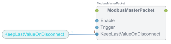
To change the default behavior so that all packet physical inputs hold their last values when the packet(s) go Offline, change the ModbusIO KeepLastValueOnDisconnect property to 1.
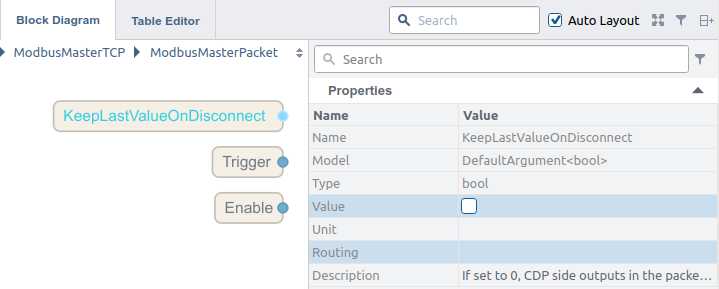
If you have KeepLastValueOnDisconnect set to 1 in the ModbusIO, and only want to change an individual packet's behavior so that it sets its physical inputs to 0 when it goes Offline, remove the Routing in the KeepLastValueOnDisconnect Argument for that packet, and set the Argument Value to 0:
See also the related topic Safe Value CDPSignals.
Modbus Slave Setup
The Modbus slave is set up from the perspective of the Modbus master. If the Modbus master has a packet with 'ReadHoldingRegisters', then the slave should also be set up with a packet with 'ReadHoldingRegisters'. The only difference is in the CDPSignalChannels' Input property, which is set up inversely to that of the Master. In other words, set up the Modbus slave packet exactly as you would set up the Modbus master packet, but make sure to invert the Input in the Modbus slave CDPSignalChannels relative to the Modbus master channels. This ensures the slave provides data for the master’s reads and accepts data from the master’s writes.
Note: If you have a Modbus master already set up, go into the Packet and copy all modules. Go into the corresponding Modbus slave packet and paste in the modules. Then go into each module in the Modbus slave and invert the Input attribute for all the channels in each module.
Get started with CDP Studio today
Let us help you take your great ideas and turn them into the products your customer will love.