Modbus Setup Guide
Introduction
This tutorial demonstrates a system that uses a Generic Modbus master and a Generic Modbus slave to transfer values between two applications in CDP Studio, the independent automation software for open PC-based real-time distributed control systems. The purpose is to show how to set up communication for both a Modbus master and a Modbus Slave. This can be useful when you want to connect your control application to another external system (like a PLC) where you can exchange data with it either as a Modbus master or a Modbus slave. Data is transferred to and from an I/O Server by setting up Routing on the signals to retrieve the values (either in control-system components or in the Modbus I/O Server).
The tutorial shows how to set up one Application with a Modbus TCP Master, and another Application with a Modbus TCP Slave. When run, values are transferred between the applications using the Modbus industrial protocol. The example uses the pre-made 2-AO-short and 2-AI-short IOModules for brevity.
See the Modbus Protocol Quick Guide for information about how Modbus works.
Set up a Test-system
First we set up a System that our Modbus component can be tested in:
Create a system named ModbusDemo with a Console application named ModbusDemoApp, then select Configure mode. See How to Create a system for more information.
Set Up the ModbusMaster Application
- Select the ModbusDemoApp that resides under ModbusDemo in the Project tree
- In the Resource tree, expand the ModbusIO resource and the 'Generic Master/Client' group
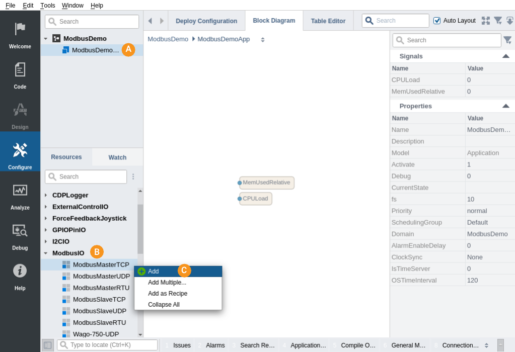
- Right-click/add a ModbusMasterTCP to ModbusDemoApp:

Note: Resources are always added as children to the currently selected item.
- Navigate into the ModbusMasterTCP that was added by double-clicking it.
- If there is a pre-defined ModbusMasterPacket called IO, skip the next two steps.
- From the Resource tree, double-click a ModbusMasterPacket to add it to the Packets section in the ModbusMasterTCPIOServer.
- In the Packets table, rename the ModbusMasterPacket to IO.
- Navigate into the IO packet by double-clicking it.
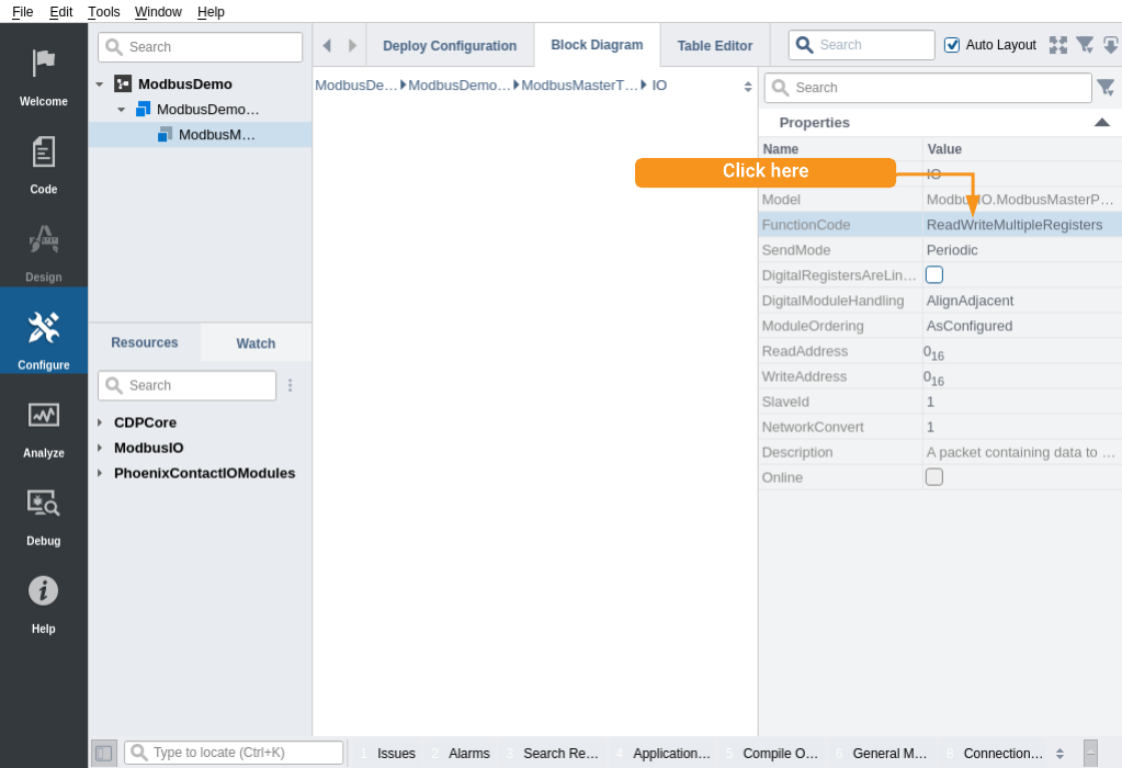
- Click in the FunctionCode column and make sure it is set to ReadWriteMultipleRegisters to both send and retrieve data:

- Set SlaveID to '1'.
- Make sure the property named ReadAddress is set to 0. This is the first Modbus address that channels are read from.
- Make sure the property named WriteAddress is set to 0. This is the first Modbus address that channels are written to.
- From the Resource tree, right-click/Add a 2-AO-short IOModule into the Module table.
- From the Resource tree, right-click/Add a 2-AI-short IOModule into the Module table.
- Double-click to navigate into the 2-AO-short.
- Set the Value of AO0 to 1
- Set the Value of AO1 to 2
Configure Where to Connect
Note: A Modbus slave is usually a physical device such as an I/O, a PLC or even an Arduino. For this example, we will set up a Modbus slave running in a separate application on the same machine as the Modbus master, and connect the Modbus master to that local Modbus slave.
We have now set up a Modbus master IOServer with an input and an output. We want it to connect to a Modbus TCP Slave on the same machine, so we set up our Modbus master to connect to that:
- Select the Deploy Configuration tab and look into the Networks table. For our test, the selected network should be 'Loopback'. Take a note of the 'IP' address (usually 127.0.0.1, but may differ), it will be used below.
- Select the ModbusMasterTCP component inside the ModbusDemoApp in the Project tree.
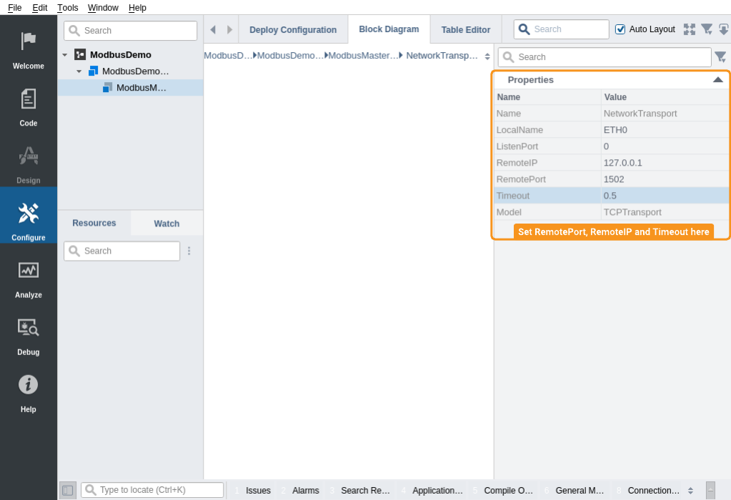
- In the Transport table, double-click into NetworkTransport, and make sure the RemoteIP of the target device is set to the same IP address that you took a note of above.
- Set RemotePort to 1502 (502 is the default Modbus port, but we are testing with a local Modbus slave, and ports below 1024 require administrative rights to open. We therefore use a non-standard Modbus port just for this testing purpose.)
- Set the Timeout to 0.5 seconds. When no packet data is received within this timeout, the IOServer will go to Offline state.

Set up the Modbus Slave Application
The Modbus slave is set up exactly the same as the Modbus master, i.e. the packet setup is identical (FunctionCode, ModuleOrdering, DigitalModuleHandling, ReadAddress and WriteAddress), but the channel Input is inverted in relation to how the Modbus master channels are set up:
Add a Console application ModbusSlaveApp as explained in Adding an Additional Application to a System.
- Select the newly added application in the Project tree.
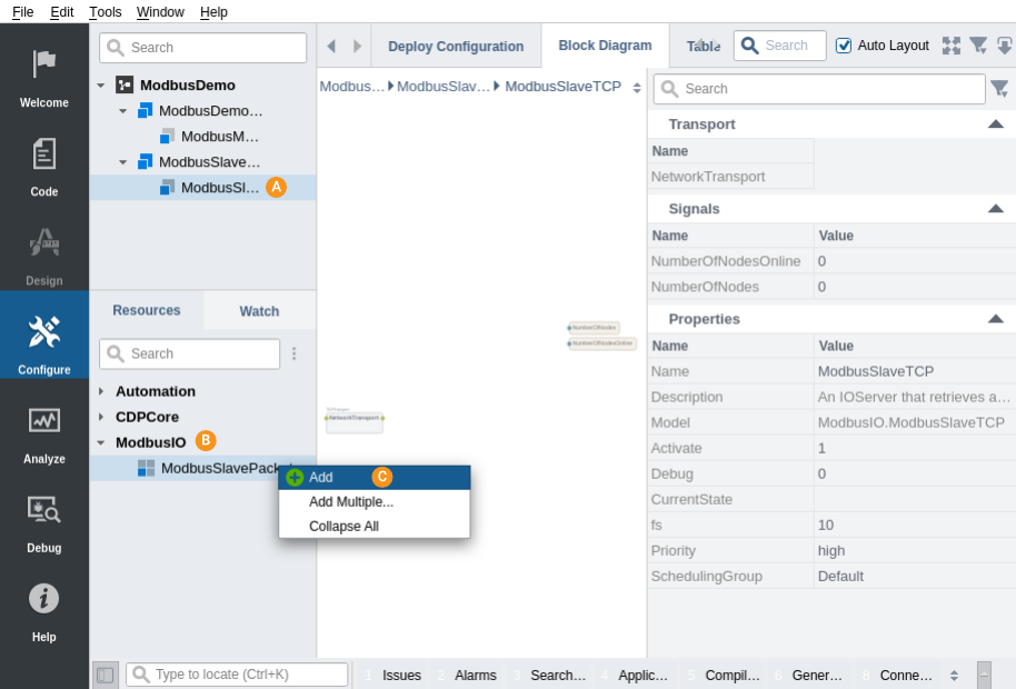
- In the ModbusIO resource in the Resource tree, in the 'Generic Slave/Server' group, right-click/add a ModbusSlaveTCP to ModbusSlaveApp.
- Click the ModbusSlaveTCP component that was added to navigate into it.
- From the Resource tree, right-click/add a ModbusSlavePacket to the Packets section in the ModbusSlaveTCP

- In the Packets table, Rename ModbusSlavePacket to IO
- Double-click on IO to navigate into the packet.
- Click in the FunctionCode column. Make sure it is set to ReadWriteMultipleRegisters for the master to access both input and output data.
- Set SlaveID to '1'.
- Make sure the property named ReadAddress is set to 0. This is the first Modbus address that channels are read from.
- Make sure the property named WriteAddress is set to 0. This is the first Modbus address that channels are written to.
- Double-click IO to go into the module configuration.
- From the Resource tree, right-click/Add a 2-AO-short IOModule into the Module table.
- From the Resource tree, right-click/Add a 2-AI-short IOModule into the Module table.
Note: The data from ModbusMasterTCP.IO.2-AO-short.AO0 will be written into the ModbusSlaveTCP.IO.2-AI-short-AI0 channel. Similarily, data from the channels in ModbusSlaveTCP.IO.2-AO-short will end up in ModbusMasterTCP.IO.2-AI-short.
This means packet setup for the Modbus master and Modbus slave is exactly equal, except that the Modbus slave requires inputs where the Modbus master has outputs, and vice versa.
Configure Connection
We have now set up a Modbus slave IOServer with inputs and outputs. Now we must set up which interface it should accept connections from:
- Select the ModbusSlaveTCP component.
- In the Transport table, set ListenPort to 1502 (the same port as specified in the ModbusMasterTCP Transport in the Modbus master configuration).
Note: To emulate a proper Modbus device, the port should be set to 502, but this might require administrator access rights. If the port is changed in the Modbus slave, make sure that the Modbus master communicates with the same port number.
How to Run the Tutorial
To run the tutorial from CDP Studio, select Configure mode, right-click on the system project and select Run & Connect. See the Running and Connecting to the System tutorial for more information.
Verify That It Works
Navigate into ModbusSlaveApp ModbusSlaveTCP IO 2-AI-short.
When communication is working correctly, AI0 should have the value 1, and AI1 should have the value 2.
Both the ModbusDemoApp.ModbusMasterTCP and the ModbusSlaveApp.ModbusSlaveTCP should have the Property CurrentState (found in the Properties table) set to Online, and data written from ModbusDemoApp.ModbusMasterTCP.IO.2-AO-short.AO0 should go into ModbusSlaveApp.ModbusSlaveTCP.IO.2-AI-short.AI0. Similarly, data written into ModbusSlaveApp.ModbusSlaveTCP.IO.2-AO-short.A00 should end up into ModbusDemoApp.ModbusMasterTCP.IO.2-AI-short.AI0.
Note: For both the master and slave you can set up many packets with different SlaveIDs and different Modbus register ranges. If a master requests data outside the allowed area, the Modbus request will not be performed by the slave and an error code will be returned.
Troubleshooting
The Application Output window contains messages from the application. 'Error' or 'Warning' messages found there indicate problems.
The master/slave is not going to Online state can typically be caused by:
- No connection between master and slave
- Incompatible ip-address ranges / ports on master and slave. The master and slave must be connected via ethernet (have access to each others subnets), and the port that the master sends to must be the port that the slave listens to.
- Data is attempted written to a ReadOnly area
- Data is attempted read from a WriteOnly area
- Data requests are made outside allowed area. For instance, if the master wants five 'unsigned short' type channels from address 2000, then the slave must have address 2000 set up with at least 10 bytes (5*sizeof(unsigned short)) worth of channels.
- The configured ethernet ports may already be in use by other services (note that ports <1024 require administrative rights to open)
- Either the Master or the Slave is Suspended
The NumberOfNodesOnline signal in the Modbus IOServer tells how may packets are actively used at any moment.
Error Messages
If the Modbus slave does not accept the request, it will respond with an error message. Typical error messages are
| Number | Name | Description |
|---|---|---|
| 01 | ILLEGAL FUNCTION | The Function code is not allowed, or the slave is not in a correct state to process it. |
| 02 | ILLEGAL DATA ADDRESS | The data address received in the query is not an allowable value for the slave. More specifically, the combination of address and length tries to access data outside the allowed area. |
| 03 | ILLEGAL DATA VALUE | A value in the query data field is not an allowable value for the slave. Typically, the length of a request can be wrong. It does not indicate faults in register-values, as the Modbus protocol does not validate register values. |
| 04 | SLAVE DEVICE FAILURE | An unrecoverable error occured while the slave attempted to perform the requested action. |
Note: More information about what is going on can be obtained by setting the IOServer Property Debug to '1' or '2', as explained in Debug Information. Remember to set it back to 0 after finding the cause of the problem.
Get started with CDP Studio today
Let us help you take your great ideas and turn them into the products your customer will love.