Basic Function Block Tutorial - Motor Start/Stop and Ramp
Why This Tutorial
This is a hands-on exercise for learning Basic Block configuration in Configure mode. You will create a practical control setup: a small motor controller state-machine and an external actuator path with start, stop, ramp-up, and ramp-down behavior.
The tutorial is progressive. Each step adds a small set of concepts and keeps the previous setup.
Prerequisites
- Open a system in Configure mode.
- Have one application component where you can add blocks (for example
App.Controller).
Step 1 - Create a Minimal Two-State Motor Block
Goal
Build a block that switches between Stopped and Running using events.
Step-by-Step
- In the Project tree, select the component where you want to add the controller block.
- In the Resource tree, find Sequencer -> BasicBlockHelpers and right-click Sequencer.BasicBlock_2S, then select Add.
Note: The Sequencer.BasicBlock_2S is a BasicFunctionBlock that is already set up with two states and transitions between them to make it easier to get started.
- Rename the added block to
MotorCtrl. - Double-click
MotorCtrlto navigate into it. - In the Resource tree, right-click Sequencer.EventIn and select Add.
Note: Sequencer.EventIn is used to receive messages as events and trigger state-machine processing. In addition to being pure triggers, the events can bundle
Datathat will be unpacked to all matching (by name) local Arguments in the object containing the Event. - Rename it to
Start. - Add another Sequencer.EventIn to
MotorCtrl, and name itStop. - Rename states:
Null-> StoppedWork-> Running
- Rename transitions:
ToWork-> ToRunningToNull-> ToStopped
Note: Renaming states and transitions early keeps the Execution Control Chart (ECC) self-explanatory and makes later routing and troubleshooting easier.
- Connect events to transitions:
StarttoToRunningStoptoToStopped
You can do this either by dragging a route in the block diagram or by setting the transition
Routingproperty.
Run & Test
- Make sure
MotorCtrl.ProcessOnis set toEvent.Note: ProcessOn can handle two processing modes: Event-based and/or Cyclic. Events are occasional and message-driven, while Cyclic triggers at a repeated deterministic interval.
- Select the system in the Project tree and choose Run & Connect.
- Navigate into
MotorCtrl. - Select the
Startevent, and in theMessagestable, right-click0x20100and select Add to Watch -> Add. - Do the same with the
Stopevent. - From the Watch list, you can now click
Sendto triggerStartandStopevents for the state-machine.
Expected Behavior
- Sending
Starttransitions the state-machine toRunning.Note: The active state is colored green, while the previously activated states are colored yellow.
- Sending
Stoptransitions the state-machine back toStopped.
What We Learned
- Creating a simple state-machine.
- Using events to control it.
Step 2 - Add Speed Arguments and Simple RunScript Actions
Goal
Make each state write a motor command value.
Step-by-Step
- Stop the system if it is currently running.
- Select
MotorCtrlin the Project tree. - In the Resource tree, right-click Sequencer.Argument<double> and select Add. Rename it to
SpeedRef. - Add a Sequencer.ArgumentOut<double> and rename it to
SpeedCmd.Note: Sequencer.ArgumentOut<> can be routed from multiple sources. We can later route the SpeedCmd from multiple states, but only the active state will update it.
- Navigate into
MotorCtrl, then select stateRunning. - In the Resource tree, right-click Sequencer.RunScript and select Add. Rename it to
SetRunCmd. - Set
SetRunCmd.Script:SpeedCmd = SpeedRef - Navigate into state
Stoppedand add another Sequencer.RunScript. Rename it toSetStopCmd. - Set
SetStopCmd.Script:SpeedCmd = 0.0
Note: RunScripts (and also RunOperations, which we introduce later) are only executed when a state-transition occurs, in this case when a Start or Stop Event triggers it. If there are extra conditions on transitions so the transition is not taken, then the current state RunScript (or RunOperation) will not run.
Run & Test
- Select the system in the Project tree and choose Run & Connect.
- Add
SpeedRefandSpeedCmdto the Watch list. - Set
SpeedRefto a non-zero value. - Trigger
Startfrom the Watch list, then triggerStop.
Expected Behavior
- When entering
Running,SpeedCmdis set toSpeedRefbecause the state-transition triggers the RunScript.Note: Changing
SpeedRefduringRunningdoes not updateSpeedCmd, becauseRunningis only executed on events in this step. - When returning to
Stoppedstate,SpeedCmdreturns to0.
What We Learned
- Adding input and output Arguments to the state-machine.
- Using RunScripts to control the Arguments.
RunScriptis excellent for short state-local logic. If logic starts growing, move it to operators for easier debugging, and useRunOperationinstead to run those operators.- Since we run the state-machine on Event, the RunScripts are only executed when the event causes a state-transition.
Step 3 - Enable Cyclic Behavior (E+C with O+P)
Goal
Run state logic on every cycle while the state remains active.
Note: Without Cyclic running, properties in the state, such as Time, are only updated on received Events.
Step-by-Step
- Stop the system if it is currently running.
- Select
MotorCtrlin the Project tree. - In the property table, set
ProcessOn= E+C, meaning:- E - Process state-machine on Event
- C - Process state-machine Cyclically (based on closest parent CDPComponent fs)
- In the property table, set
TransitionMode= O+P, which has the following meanings:- O - One transition per execution
- P - Re-Process current state when not able to transition
Note: Setting O+P makes the state-machine run similarly to the CDPComponent scheduler: select a new state (if any) and run it once, otherwise run the current state once.
Run & Test
- Select the system in the Project tree and choose Run & Connect.
- Trigger
Start. - Change
SpeedRefa few times while staying inRunning.
Expected Behavior
SpeedCmdupdates every cycle whileRunningis active.- You do not need a new event for each
SpeedRefadjustment.
What We Learned
- How to set the state-machine to run both on event and cyclically.
- O allows one transition per process call and gives predictable Execution Control Chart (ECC) stepping.
- P runs current state logic also when no transition is taken.
- This is the same transition-mode combination used in Sequencer.CyclicStateMachine and gives behavior similar to traditional cyclic CDP control blocks.
- State-properties, such as Time, are only updated on received Events in E mode but on every cycle in C mode.
Step 4 - Replace Scripts With RunOperation
Goal
Implement speed changes using OperatorContainers instead of scripts. This allows us to later add more complex operator logic.
Step-by-Step
- Stop the system if it is running.
- Select
MotorCtrland delete Stopped.SetStopCmd. - Delete Running.SetRunCmd.
- In state
Running, add Sequencer.RunOperation namedRunningCmd. - In state
Stopped, add Sequencer.RunOperation namedStopCmd. - Click into the background of the
MotorCtrlobject to change the selected object. - From the
CDPCoreresource, add anOperatorContainerand name itSetStopSpeed. - Select
SetStopSpeed, and add a Sequencer.Argument<double> namedStopSpeed. - Select the
StopSpeedArgument and make sure theInputproperty is not checked. - Make sure
StopSpeed.Valueis0. - Copy
SetStopSpeedand right-click Paste it intoMotorCtrl(select Add in the dialog box when prompted).Note: Copying
SetStopSpeedand then specializing the copy toSetRunSpeedensures both operator containers start with identical structure, which reduces setup mistakes. - Rename the pasted object to
SetRunSpeed. - Inside
SetRunSpeed, renameStopSpeedtoRunSpeed. - Select
SetRunSpeedand add a Sequencer.Argument<double>, name itRef. - Navigate into
SetRunSpeed, connect (by drag and drop)ReftoRunSpeed. - Navigate to
MotorCtrland connectSpeedReftoSetRunSpeed.Ref. - Connect
Stopped.StopCmdtoSetStopSpeed. This makes theStoppedstate invoke this operator. - Connect
Running.RunningCmdtoSetRunSpeed. - Connect
SetRunSpeed.RunSpeedtoSpeedCmd. - Connect
SetStopSpeed.StopSpeedtoSpeedCmd.
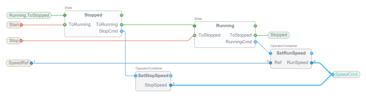
The final MotorCtrl should look something like this:
Run & Test
- Select the system in the Project tree and choose Run & Connect.
- Trigger
Start, then triggerStop.
Expected Behavior
- SpeedCmd changes according to
StoppedandRunningstate, just like it did in Step 3.
What We Learned
- How to replace state-local scripts with RunOperation nodes.
- How each state can invoke a dedicated OperatorContainer for clearer structure.
- How
Sequencer.ArgumentOut<double>can receive values from multiple sources, while active state logic decides what is written. - Why this keeps
MotorCtrlfocused on decisions, while actuator dynamics are moved out in Step 5.
Step 5 - Move Ramping to an External Actuator Path
Goal
Keep MotorCtrl focused on state-machine decisions and move ramp/filter dynamics outside.
Step-by-Step
- Stop the system if it is running.
- In the same parent component as
MotorCtrl, add a CDPCore.OperatorContainer and name itMotorActuator. - Navigate into
MotorActuator. - Add Sequencer.Argument<double> for input and output:
TargetSpeed(Input=1)ActualSpeed(Input=0)
- Add Automation.RampFilter<double> named
SpeedRamp. - Set
SpeedRamp.MaxRatevalue to0.5. - Connect routes in
MotorActuator:TargetSpeed-> SpeedRamp.InSpeedRamp.Out-> ActualSpeed
- Navigate back to the parent component and select
MotorCtrl. - Add a Sequencer.Argument<double> named
SpeedFeedback.Note:
SpeedFeedbackis introduced here so Step 6 can use measured speed in transition conditions, instead of relying only on commanded values. - Navigate back to the parent component (e.g. double-click the background) and route:
MotorCtrl.SpeedCmd-> MotorActuator.TargetSpeedMotorActuator.ActualSpeed-> MotorCtrl.SpeedFeedback
- Keep
MotorCtrlstate logic from Step 4 unchanged.
Run & Test
- Select the system in the Project tree and choose Run & Connect.
- Add
MotorActuator.TargetSpeed,MotorActuator.ActualSpeed, andSpeedRamp.MaxRateto the Watch list. - Right-click
MotorActuator.ActualSpeedand add it to a Plot. - Right-click
MotorActuator.TargetSpeedand add it to a Plot. - Go into Analyze mode.
- Trigger
StartandStopfrom the Watch list as before. - Watch the target and actual speed response.
Expected Behavior
MotorCtrl.SpeedCmdchanges by state, just like in Step 4.MotorActuator.ActualSpeedfollowsTargetSpeedwith ramp-limited dynamics.- State logic and physical response are now separated and easier to maintain.
What We Learned
- The state-machine should express control intent, not physical dynamics.
- Ramp/filter/simulation belongs naturally in an external actuator path.
- You can experiment with e.g.
IIRFilterand other operators to simulate different motor output behaviors. - This separation makes
MotorCtrlreusable for different actuator models.
Step 6 - Expand to a Practical Motor State-Machine
Goal
Make the controller robust with startup, stopping, and fault handling.
Step-by-Step
- Stop the system.
- Navigate to
MotorCtrl. - Add one more Sequencer.EventIn named
Reset. - Add Sequencer.InternalArgument<double> nodes needed for transition conditions:
StartTimeoutSec(5 seconds) andStopTimeoutSec(5 seconds)Note: Explicit timeout arguments make fault escalation deterministic and easy to tune without changing transition expressions. Using InternalArgument keeps these tuning values local to
MotorCtrland out of the block's external API. - Add states
Starting,Stopping, andFault. - In
Stoppedstate, renameToRunningtoToStarting, and connect it toStartingstate. - Add a Sequencer.StateTransition
Starting.ToRunningand connect it toRunningstate. - Add a
Sequencer.RunOperationtoStarting, and name itRampRun. - Connect it to
SetRunSpeed. - Select
Starting.ToRunning, and inValue, putSpeedFeedback >= SpeedRef - 0.05
- In
Runningstate, renameToStoppedtoToStopping, and connect it toStoppingstate. - Add a Sequencer.StateTransition
Stopping.ToStopped. - Select
Stopping.ToStopped, and inValue, putSpeedFeedback <= 0.05
- Connect
Stopping.ToStoppedtoStoppedstate. - Add a
Sequencer.RunOperationtoStopping, and name itRampStop. - Connect it to
SetStopSpeed. - In
Startingstate, add a Sequencer.StateTransitionToFault. - Select
Starting.ToFault, and inValue, putStarting.Time > StartTimeoutSec
- Connect
Starting.ToFaulttoFaultstate. - In
Stoppingstate, add a Sequencer.StateTransitionToFault. - Select
Stopping.ToFault, and inValue, putStopping.Time > StopTimeoutSec
- Connect
Stopping.ToFaulttoFaultstate. - In
Faultstate, add a Sequencer.StateTransitionToStopped, and connect it toStoppedstate. - Connect
ResettoFault.ToStopped.
Note: Make sure to rearrange the state nodes in the MotorCtrl Block Diagram ExecutionControl table so they flow nicely from left to right. The state order should be: Stopped, Starting, Running, Stopping, Fault.
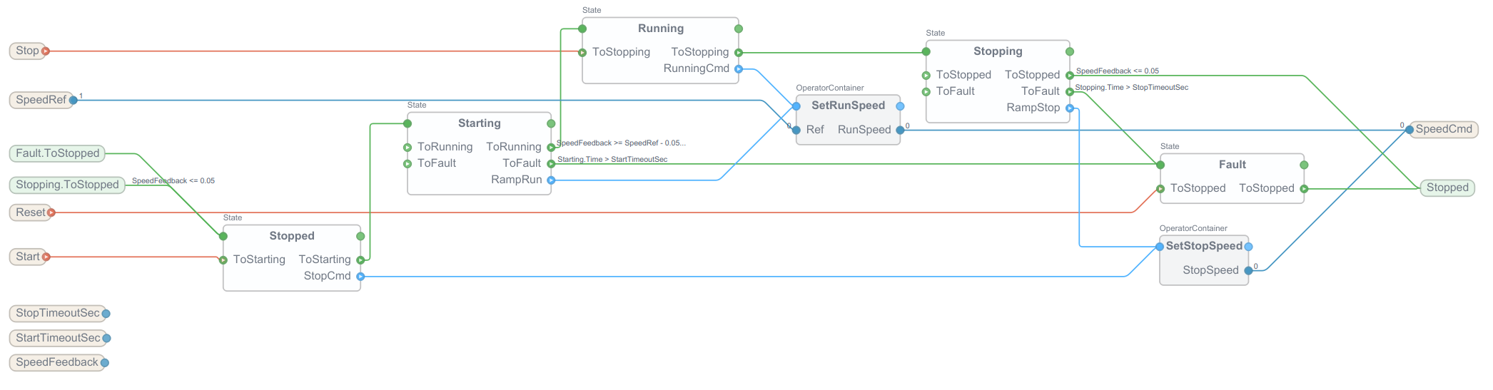
The final block-diagram for MotorCtrl should look something like this:
Run & Test
- Select the system in the Project tree and choose Run & Connect.
- Verify normal start and stop.
- Force a startup timeout condition (e.g. adjust ramp filter) and verify transition to
Fault. - Force a stopping timeout condition and verify transition to
Fault. - Select the
Resetevent, and add0x20100to the Watch list. - Trigger
Resetfrom the Watch list and verify return toStopped.
Expected Behavior
- Normal operation reaches
Runningonly when feedback confirms target speed. - Normal stop reaches
Stoppedonly when feedback confirms near-zero speed. - Fault handling is deterministic and recoverable.
What We Learned
- How to use both event-triggered and condition-triggered transitions in one state-machine.
- How to supervise start/stop behavior with
<State>.Timetimeout conditions. - How to recover from
Faultstate via explicitResetevent.
Troubleshooting
- If transitions do not trigger, confirm event routing and transition
Valueexpressions. - If time-based transitions never fire, verify
ProcessOnincludesC. - If state logic runs only on transitions, verify
TransitionModeincludesP. - If output jumps instead of ramps, verify actuator path routing through
MotorActuator.SpeedRamp.
Summary
You now have one complete pattern that scales:
- Start from event-driven two-state ECC.
- Add state-local scripts for fast iteration.
- Enable cyclic behavior with
E+CandO+P. - Move state output dynamics to an external actuator path for better separation.
- Extend to production-style states with timeout and fault handling.
For full element and property reference, see Basic Function Block.
Get started with CDP Studio today
Let us help you take your great ideas and turn them into the products your customer will love.