How to Use Composite Interfaces
How to Use Composite Interfaces
This tutorial will give you an overview of how to use the CDPPort to control on which side the port is on in block diagram components, and how to control port data direction in CDP Studio. The CDPPort can provide similar functionality as the PLC STRUCT type in IEC 61131-3 languages, which is used for input/output variables to allow simplified multi-value connections.
We will guide you through creating a switchable port-based interface for things that turns on and off, like lamps and motors, etc. Further, we will instruct you on creating a group switch component that automatically supports adding multiple switch ports. We will also set up a switchable device component to represent lamps and create a GUI and a simple test component to test group switching.
When running the system, you will see the test component automatically test the switch functionality and then use the GUI to verify that the group switching works as expected.
By completing the tutorial, you will learn the following things.
- To use CDPPort in two different ways
- Learn how to control whether a port is an input or an output in a component
- What RoutingType Push is and how to use it
Recommended: Look into Intro 3: Tutorial of Making Reusable Objects in C++.
Project Overview
The project consists of a simple GUI that contains two buttons called On, Off and three lamps. There is also a second application for the group switch and three lamp components, and the third application for a test component.
Creating the Library for Switchable Devices
When creating a library of reusable components, ports, etc its important to have clear goals and to think trough how the objects work and communicate.
In our case we are to control a group of lamps with separate On and Off buttons:
- When the user presses the On button, all devices in the group should be turned on.
- When the user presses the Off button, all the devices in the group should turn off, regardless of the On button state.
We should also consider that the Lamps in question may have a different and slower cycle frequency fs.
It is a good design practice to contemplate other possible use cases and control blocks that are needed in the future to avoid needing to change any of the prior work. For instance, we know there will be a sequencing switch to turn all the devices on and off in a sequence, so we can keep this in mind when designing the interface.
When we want many different control blocks and many different devices to communicate, we should define a unified interface for them to communicate over. We will define our interface from the perspective of the switchable device in a generic way, as we may also need to switch motors or pumps with the same interface. Thus, we name the interface Switchable. To turn the device on and off, it should have TurnOn and TurnOff inputs, and an IsOn output to know when the device has seen our input signals.
CDP already has an object for creating interfaces/ports like this, called CDPPort.
Creating the Library and Switchable Port
We will now create such an interface from the CDPPort model into a library.
- Create a new CDP library and name it Switchables
- Run the Add new... wizard on the library and add a CDP Port Model called Switchable to the library
- In Configure mode select the Switchable model in the library
- Delete the UserProperty in the Attributes Section.
- Add 3 new PropertyAsAttribute Type bool items into the Attributes Section called TurnOn, TurnOff and IsOn.
Note: The added attributes are also automatically added to the Connections Section. This table defines which properties make up the port interface and their direction. Remember that we define the interface from the switched device's perspective.
- Uncheck the Input column for the MapIsOn connection, as this will be an output for the switched device.
- Build the library.
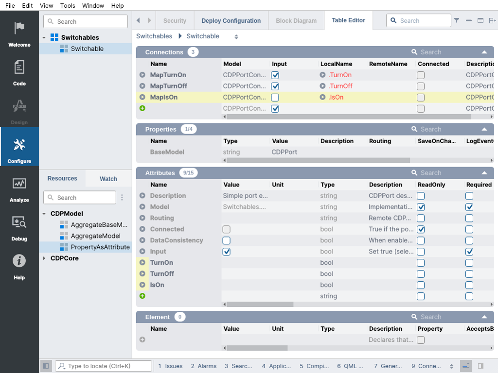
By default, CDPPort based interfaces are considered to be inputs for the component they are added to. This works well for our lamps, as there we need the Switchable port to be an input to our lamp device. But the opposite will be true for the group switch: as the switch controls all the connected lamps, we would prefer them to be considered outputs of the group switch component. The input/output side selection can be forced by setting the Input attribute on the port. The value of the Input attribute is used to choose the input/output side for the items in the port. It is also worth knowing that the input/output side does not affect how the port works in your component. This information is used for example by the Block Diagram view to show the inputs and outputs on the blocks.
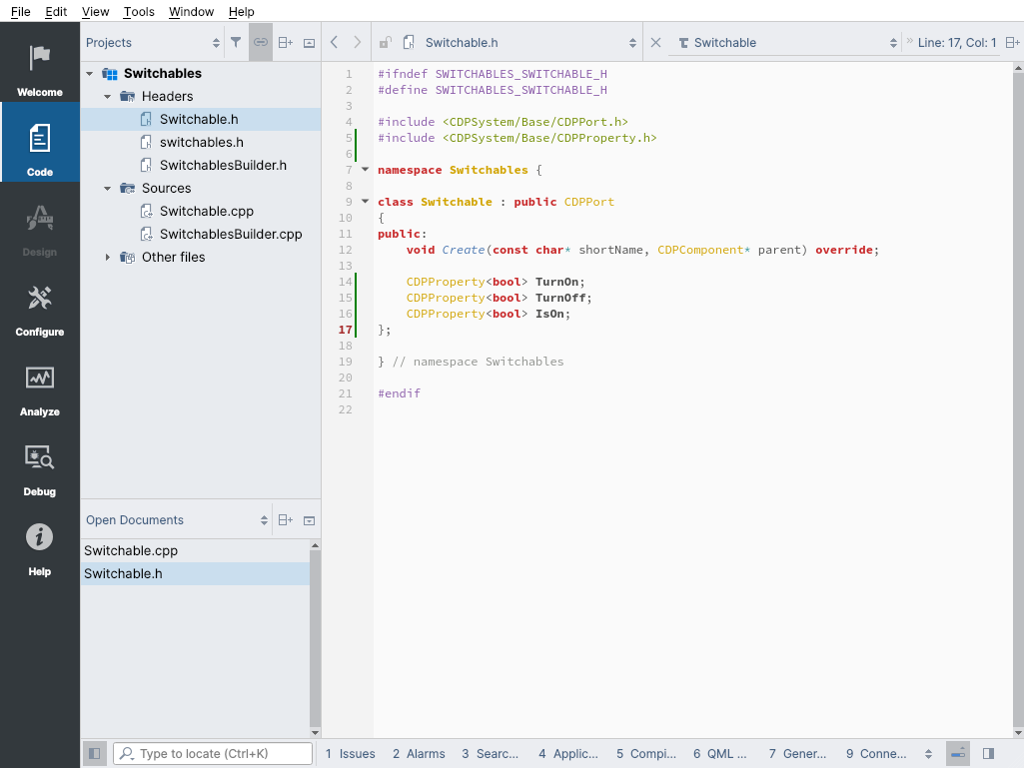
To look at the generated code for the port object: While the Switchable model is selected in the library, you may now press the F2 key to navigate to the source code. You can then toggle between the C++ header and source file with the F4 key. We don't need to do any coding here. All that is needed has already been auto-generated for us.
Creating the SwitchableDevice Component
We will now create a component to represent the lamps in our project. Switch back to Configure mode for the next steps. Make sure you have built your library after doing the changes described in the previous paragraph.
- Run the Add new... wizard on the library and add a CDP Component Model called SwitchableDevice to the library
- Switch back to Configure mode by pressing the Ctrl + 4 shortcut key
- Select the SwitchableDevice in the Switchables library
- Add a CDPSignal<bool> named On to the Signals Section
- From the Resource tree Switchables library, add a Switchable port to the SwitchableDevice
- Rename the port to Switch
- Set the fs in the Element Section to 100
- Navigate to the source of the SwitchableDevice by pressing the F2 key on the selected model
- Add code to handle setting and resetting of the On signal based on Switch port values.
For this simple component we will just add some code into the default pre-generated Null state processing function called ProcessNull:
void SwitchableDevice::ProcessNull()
{
    if (Switch.TurnOff)
        On = false;
    else if (Switch.TurnOn)
        On = true;

    Switch.IsOn = On;
}
Note: Note that we also added an assignment of the Switch.IsOn status from the On signal so that the other side of the port connection can see the status change.
- Build the library again to see that everything builds and that there are no errors.
Creating the GroupSwitch Component
We will now create the GroupSwitch component, but our initial specification did not tell how many devices the group switch should support. The pitfall in such a situation is to make a group switch with some hard-coded number of ports. It would not be a good approach, as we might need a different number of ports in the future, forcing us to go back and fix the mistake. The result is extra work, and we could then end up with several versions of the GroupSwitch component. We will likely end up with code that is hard to maintain.
We should future-proof our objects and remove the need to have unused bits cluttering the projects. This approach may sound complex, but the reverse is true; making components generic often simplifies the code.
- Run the Add new... wizard on the library and add a CDP Component Model called GroupSwitch to the library
- Switch back to Configure mode by pressing Ctrl + 4 shortcut key
- Select the GroupSwitch in the Switchables library
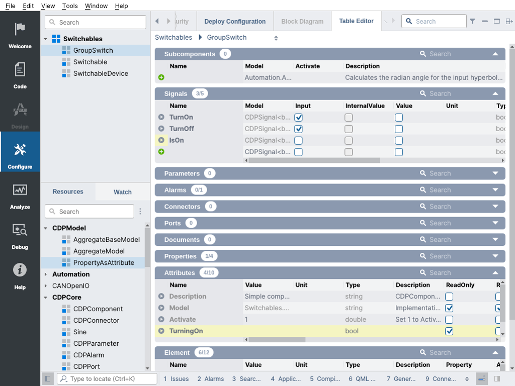
- Add three objects of type CDPSignal<bool>, named TurnOn, TurnOff and IsOn to the Signals Section
- Check the Input column for TurnOn and TurnOff
- Set the fs in Element Section to 100
- From the Resource tree CDPModel add a PropertyAsAttribute, name it TurningOn, set the Type to
booland tick the ReadOnly column.
We will now add a std::vector container to hold the generic number of ports that users may add to our GroupSwitch Component.
- Navigate to the source of the GroupSwitch by pressing the F2 key on the selected model
- Switch to the header file by pressing the F4 key
- Add our include line for our port type after other include directives in the beginning of the file starting with "#include":
#include <Switchable.h> - Add the container variable on a new line after the CDPProperty variable TurningOn:
std::vector<Switchable*> switches;
We will now add code to fill the container with the ports that the user has added to the component. This information is available after the Configure() function of the component has finished, so we will add the code to the end of the Configure() function.
- Switch back to the source file by pressing the F4 key
- To fill the container with ports of type Switchable that are retrieved from the port list m_ports in the GroupSwitch component after it has read its configuration, add the below code:
void GroupSwitch::Configure(const char* componentXML)
{
    CDPComponent::Configure(componentXML);
    for (CDPPort* port: m_ports)
        if (Switchable* switchable = dynamic_cast<Switchable*>(port))
            switches.push_back(switchable);
}
- Add code to the ProcessNull() function to control the added ports based on input signals to our component:
void GroupSwitch::ProcessNull()
{
    if (TurnOff)
        TurningOn = false;
    else if (TurnOn)
        TurningOn = true;

    if (switches.size())
        IsOn = true;
    for (Switchable* switchable: switches)
    {
        if (!switchable->IsOn)
            IsOn = false;

        if (TurningOn && !switchable->IsOn)
            switchable->TurnOn = true;
        else
            switchable->TurnOn = false;

        if (!TurningOn && switchable->IsOn)
            switchable->TurnOff = true;
        else
            switchable->TurnOff = false;
    }
}
Note: Note that we also added an IsOn signal that collects the status of the IsOn property of every port for completeness.
- Build the library to verify that everything builds and there are no errors.
Creating the Control System
To see how our created models work, we need to create a system with the required applications. We need to initially create a GUI application and a control application for our GroupSwitch and three SwitchableDevice objects emulating lamps.
- Create a new CDP system, name it SwitchDemo and name the default Console application Control
- Run the Add new... wizard on the system and add a CDP Application, choose GUI as Application Type and name it GUI
- Select the GUI application and go to Design mode
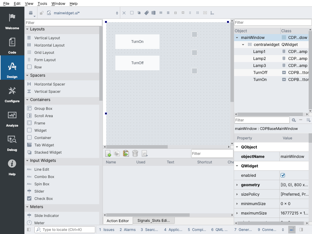
- Add two Button widgets, double click and edit the texts to be "TurnOn" and "TurnOff"
- Rename the button widgets themselves to "TurnOn" and "TurnOff"
- Add three Lamp widgets and rename the widgets to "Lamp1", "Lamp2", "Lamp3"
- Go back to Configure mode and select the Control application
- Add a GroupSwitch from Resource tree
- Use the Add Multiple... context menu on the SwitchableDevice in the Resource tree, set count to 3 and base name to "Lamp1"
- Select the GroupSwitch in the Project tree
- Use the Add Multiple... context menu on the Switchable resource, set count to 3 and base name to "Switch1"
- Enter each added port and in the Properties Section uncheck the Input property
When we removed the Input flags above, the added Switchable ports on the GroupSwitch are now considered to be outputs. As shown, no additional programming is needed to add more lamps under the GroupSwitch control. Its simple to just add one more port to the GroupSwitch and an additional lamp when needed.
- Select the Control application in the Project tree
- Use the Editor Selector to switch to the Block Diagram view
- Click and drag connections between the GroupSwitch ports and lamp ports
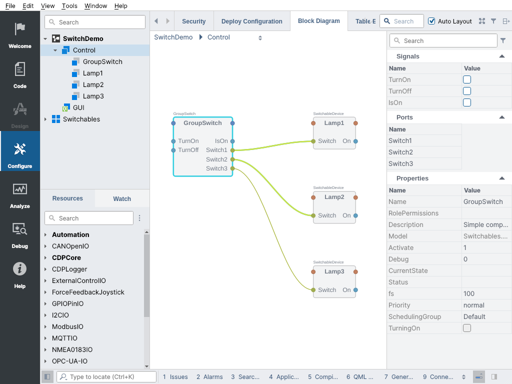
You may also switch to the Table Editor at this point to see how the connection was made. When you look at the lamp components, the Switch port now has a Routing set. So in this case, as the lamp components have the routing, their Connections table defines the data directions for the port (TurnOn and TurnOff are inputs for the lamp and IsOn is a output). This also means the lamps know there exists a GroupSwitch component where they are getting the data from.
This data dependency is also the reason for the order of the components in Control application. Your data sources should be before your data sinks in the component list to have the smallest data propagation latency. If you have many data sources and one sink component you may consider also moving the sources under the sink component to create a single structural unit.
Before it is possible to test the system, the GUI application also needs to be connected up.
- Right click on the GroupSwitch input TurnOn port circle and select Copy Path
- Select the GUI application in the Project tree and go to Design mode
- Select the TurnOn widget and paste the copied path to its cdpPressedRouting property
- Select the TurnOff widget and paste the copied path to its cdpPressedRouting property and edit the end to be "TurnOff"
- Go back to Configure mode and select the Control application in Project tree
- Right click on Lamp1 output On port circle and select Copy Path
- Select the GUI application in Project tree and go to Design mode
- Select the Lamp1 widget and paste the copied path to its cdpStyleRouting property
- Select the Lamp2 widget and paste the copied path to its cdpStyleRouting property and edit the lamp name in the path to be Lamp2
- Select the Lamp3 widget and paste the copied path to its cdpStyleRouting property and edit the lamp name in the path to be Lamp3
- Go back to Configure mode
- Run the system and wait for all applications to start up and become connected.
You can now try turning the lamps On and Off with the buttons. As a more interesting test you can try to set the fs properties of the three lamps in the Control application. Go to Configure mode and select each lamp and set different fs values: 100, 10, 1 for example. Try the GUI buttons again multiple times. You can see the lamps still all turn on, but with a delay, as the 1Hz cycle is much slower. Without our control component this lamp could miss a quick button press from the GUI.
Note: Remember that when you want to keep the changes you did on the Control application during runtime when connected, you need to Right click and select Fetch Configuration on it after stopping the system.
Adding a Tester Component
Sometimes during development it is faster to create a small tester component to verify the functionality rather than manually testing it all the time. We will do this for our little system just for fun. We will test if the GroupSwitch is able to switch on the lamps. We also don't want the existing system to know that we have a test for it, as mixing test configuration with real system can lead to many problems.
- Stop the system if you already haven't done so
- In Configure mode add a new Threaded Component Model to the Switchables library by Right clicking on the library name and choosing Add new...
- Name it Test and set the fs property to 100
- Switch to the header file by pressing the F4 key and Right click on the m_counter signal, then choose CDP > Remove from context menu
- Go back to Configure mode and select the Test component
- Add a Switchable port from the Switchables library into the Test component, name it TestPort
- Add two CDPAlarm items from CDPCore library, name them TestPassed, TestFailed
- Set the TestPassed level Notify and TestFailed level Error
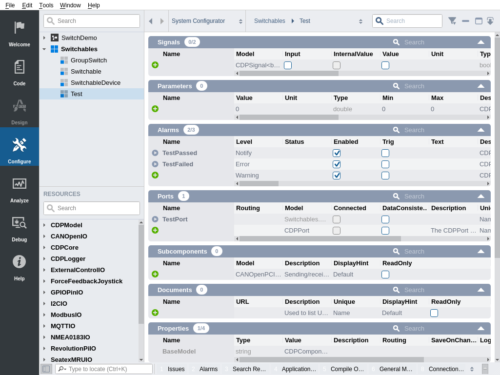
We have created the GroupSwitch component on purpose with the same signal names as the Switchable port data members. This will allow us to connect the TestPort in our Test component directly to the GroupSwitch component in our system. It is worth keeping in mind that CDP ports can connect to any object that have the same data member names available, without additional connection mapping in the port object.
The TestPort we have added is currently an input to the Test component because it has an Input property that is set. If we would add it to our system we could connect the GroupSwitch component to the TestPort and all requirements would be fulfilled. The TestPort would have the routing to GroupSwitch and our existing system would not know the test component exists. But it would look like the Test component is controlled by the GroupSwitch because of the dependency direction.
In cases like this where you need the data dependency to be one way but the seeming control direction needs to be different, you can add a hint about this to the port variable in the components model in the library.
- Select the Test component in the library
- Press the in front of TestPort
- From the table filter uncheck Hide Base Model Items option (See filter help)
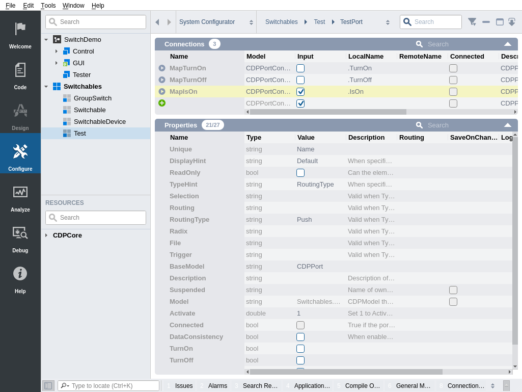
- In the Properties Section change the value of TypeHint to be RoutingType
- In the Properties Section change the value of RoutingType to be Push
- In the Properties Section change the value of Input to be unchecked
- To correct the data direction for the test also uncheck the Input of MapTurnOn and MapTurnOff and check Input of MapIsOn
This tells the Block Diagram view that the port is an output for theTest component but when the connection is made, the routing should still be set on the TestPort because it is a Push routing. Now it will look like the Test component controls the GroupSwitch but the data connection is actually in the reverse direction.
- Select the Test component in the library and press the F2 key to navigate to its code
- Replace the Main() function with the following code:
void Test::Main()
{
    while(!Stopped())
    {
        m_event.Wait();
        m_event.Reset();
        if (!TestPort.IsConnected())
            continue;

        if(!Stopped())
        {
            CDPMessage("Start test switching run.\n");
            RunInComponentThread([&] () { TestPort.TurnOn = true; });
            OSAPISleep(200); // sleep 200 milliseconds
            RunInComponentThread([&] () { TestPort.TurnOn = false; });
            OSAPISleep(2000); // sleep 2000 milliseconds
            RunInComponentThread([&] () { if (!TestPort.IsOn) TestFailed.Set(); });
            RunInComponentThread([&] () { TestPort.TurnOff = true; });
            OSAPISleep(200); // sleep 200 milliseconds
            RunInComponentThread([&] () { TestPort.TurnOff = false; });
            OSAPISleep(2000); // sleep 2000 milliseconds
            RunInComponentThread([&] () { if (TestPort.IsOn) TestFailed.Set(); });
            OSAPISleep(1000); // sleep 1000 milliseconds
            CDPMessage("Test switching done.\n");
            if (!TestFailed.IsSet())
            {
                RunInComponentThread([&] () { TestPassed.Set();});
                CDPMessage("TEST PASSED!\n");
            }
            else
                CDPMessage("TEST FAILED!\n");

            RunInComponentThread([&] () { TestPort.Disconnect(); });
            RunInComponentThread([&] () { Stop();});
            OSAPISleep(1000); // sleep 1000 milliseconds
        }
    }
}
You may now build the library before using the Test component in the system.
- In Configure mode add a new console application by Right clicking on the system and selecting Add new..., name it Tester
- Select the Tester application and switch to Block Diagram view
- Drag in the Test component to the Tester application
- Click on the TestPort port circle and select Copy Path
- Select the Control application
- On the GroupSwitch input port circle, right click and select Connect From Control.GroupSwitch
- Run the system
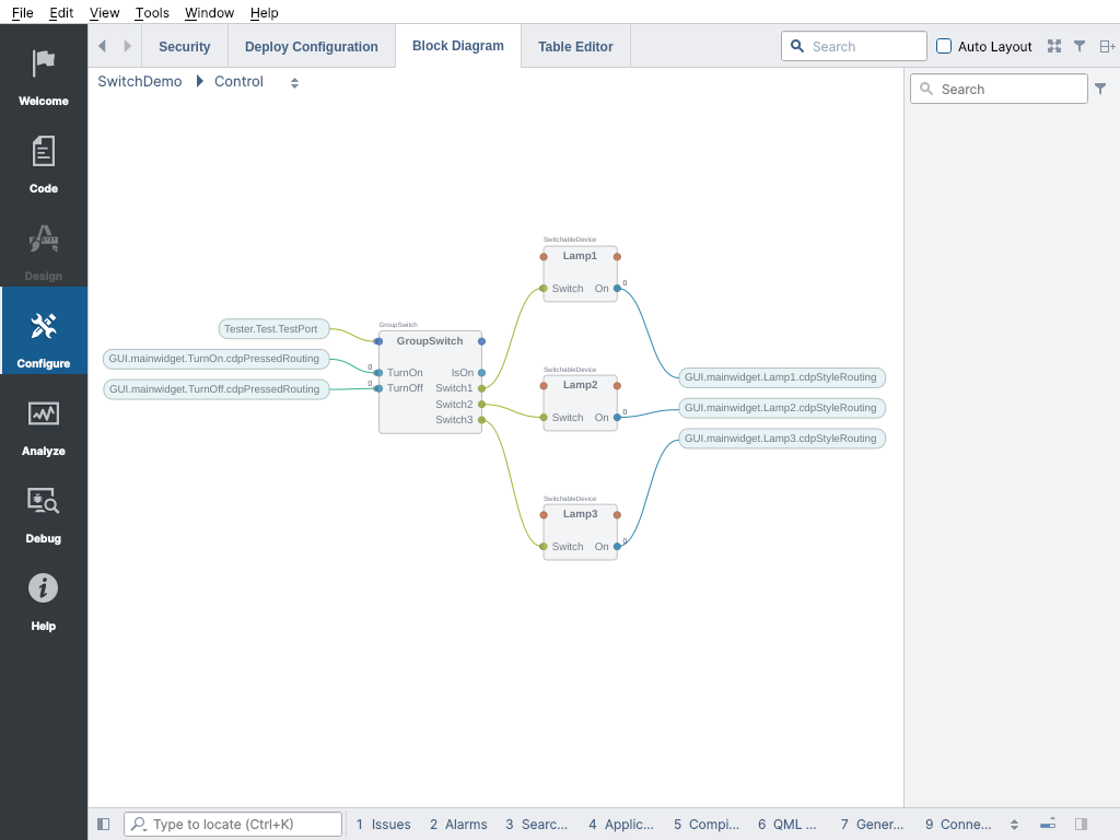
You have now connected the data from the GroupSwitch to the TestPort. When you run the system, the Test component will connect to the GroupSwitch and after connecting it will switch the GroupSwitch on and off once, you will see this happen in the GUI application and then disengage from the rest of the system. You can avoid running the Tester application by running the GUI and Control applications separately and then connecting the system.
Congratulations!
You should now be able to get the most out of CDPPort in your systems! You can now proceed to the next tutorial.
Get started with CDP Studio today
Let us help you take your great ideas and turn them into the products your customer will love.