Using Wago PFC 200 With IO Modules and WebUI
Introduction
This example demonstrates configuring and using a Wago PFC200 controller with digital and analog I/O modules to build a basic control system. It includes a Web UI to read and set the I/O values, as the Wago device lacks a built-in display port.
This example explains:
- Configuring the Wago PFC controller
- Adding the Wago PFC IO server and I/O modules to the system
- Connecting data from the I/O module channels to the control system
- Scaling analog values from raw input values to meaningful control system values
- General recommendations and tips
Project Overview
The project utilizes a Wago PFC 200 controller and 4 I/O modules: digital input, digital output, analog input, and analog output. The analog values are scaled from the physical I/O module value to meaningful control system values.
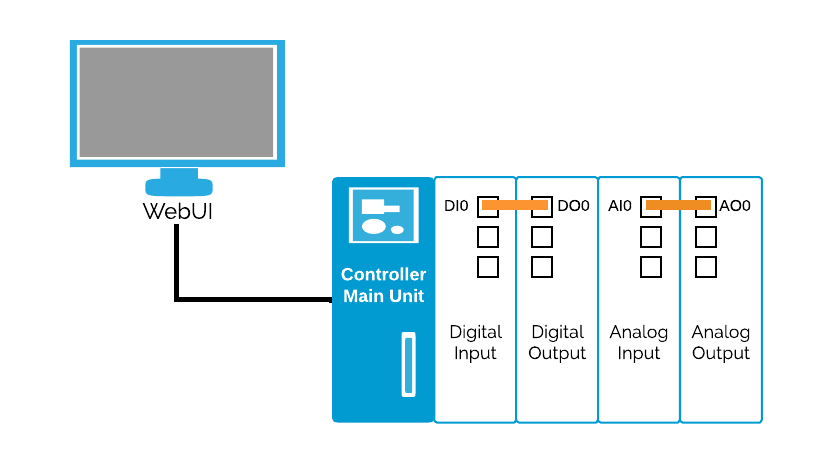
Wires connect the digital output channel DO0 to the digital input channel DI0, and the analog output AO0 to the analog input AI0 channel. This enables setting a value on the output and reading the value on the input channel.
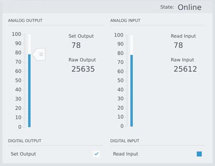
The WebUI allows you to set values on the output channels and display the values read from the input channels. Note that raw analog values may differ between input and output cards. See the Wago documentation for details on this behavior.
How to Run the Example
To run the example from CDP Studio, open Welcome mode and find it under Examples. Next, in Configure mode right-click on the system project and select Run & Connect. See the Running the Example Project tutorial for more information.
The system runs on a Wago PFC; therefore, you must go to Configure mode, select Deploy Configuration, pair the Wago, and select the Wago as the device. Use the toolchain WAGO ARMv7 32-bit Toolkit.
The Wago PFC setup is covered in the Toolkit documentation; refer to the Wago Image Setup section in the WAGO ARMv7 32-bit Toolkit documentation for detailed steps.
The WebUI starts after the application runs on the controller and CDP Studio will connect to the running application. In Configure mode, select the application, either in the Block Diagram or Table Editor, scroll down in the property list, find the WebURL property, paste the URL into your browser, or click on the small globe icon.

Project Description
The hardware used is a Wago PFC 200, and the following I/O modules are installed in this order:
- 750-430 Digital Input
- 750-530 Digital Output
- 750-459 Analog Input
- 750-550 Analog Output
This project uses a three-layer architecture, separating the application layer from hardware-specific elements for modularity and easier maintenance. This separation allows you to change the controller or modules without affecting the application itself, avoiding physical dependencies or raw analog values within the application logic.
The WebUI connects to the control system in the application layer. Through the WebUI, you can set the analog output value, SetAnalogOut, from 0 to 100 using a slider; this value is then scaled to the correct I/O module raw value, AnalogOutRaw. The analog output is physically wired to the analog input, and the analog input I/O module reads the value, which is displayed in the WebUI as ReadAnalogIn and AnalogRawIn.
Similarly, you can set the digital output using a checkbox and see the corresponding digital input value.
You can modify the example if you do not have identical I/O modules. Just replace the modules, move the routings and make sure that you update the scaling points matching your I/O module.
Important Concepts and Recommendations
Relation Between Physical Connectors and Logical CDP Signals
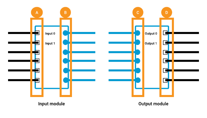
The following figure shows a simplified representation of input and output I/O modules. Physical wires connect to the left side () for input modules, while CDP signals are output on the right (). For output modules, you connect values to CDP input signals on the left side of the I/O block ().
Scaling the Analog Physical Values
Analog I/O modules measure or set values, e.g. from 0 to 10 V. These modules use raw values, such as setting 0 to represent 0 V and 32767 for 10 V. Check the Wago documentation for module-specific details, often found in the Process Image section. Converting these values to meaningful application-specific units is recommended.
For example, to set the speed in rpm, then 0 V = 0 rpm and 10 V = 100 rpm, use a Signal in your application with a value range of 0-100 and then use the scale operator to transform the sensible application value to the raw I/O value when writing to the I/O module.
Get started with CDP Studio today
Let us help you take your great ideas and turn them into the products your customer will love.