I2C I/O Communicating with Arduino compatible microcontrollers
Prerequisites
In order to continue with the instructions below you need to make sure that you have enabled SSH and I2C on the device you will be deploying to.
Setting up the project in Studio
Adding the I2CIOServer
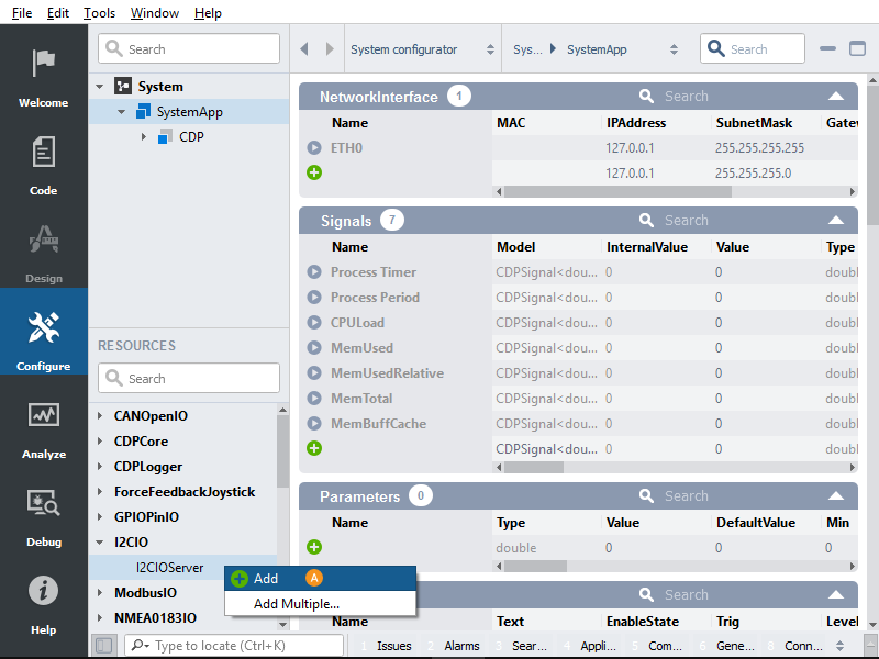
First, we add an I2CIOServer component to our system.
Selecting the I2C adapter
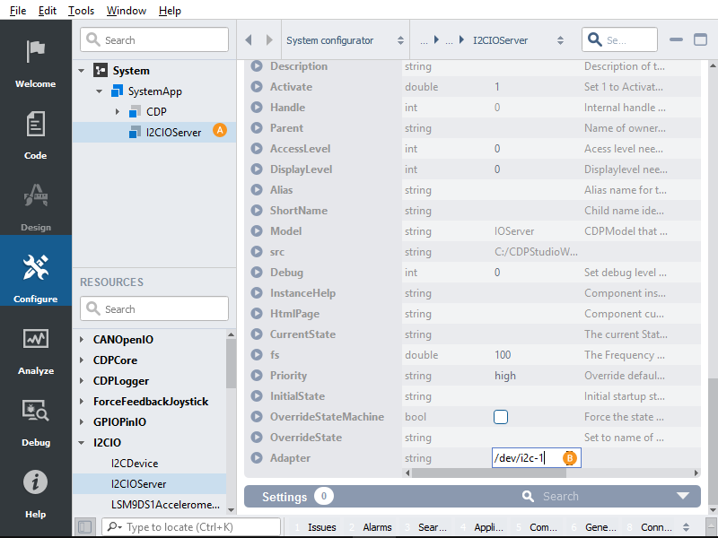
Then we enter the component.
We need to scroll down to properties and enter the correct i2c adapter.
Note: You can run "i2cdetect -l" from the terminal to list the available i2c adapters. If you can not see any available adapters then make sure that you have enabled the I2C and reboot.
Adding our I2CDevice (The Arduino)
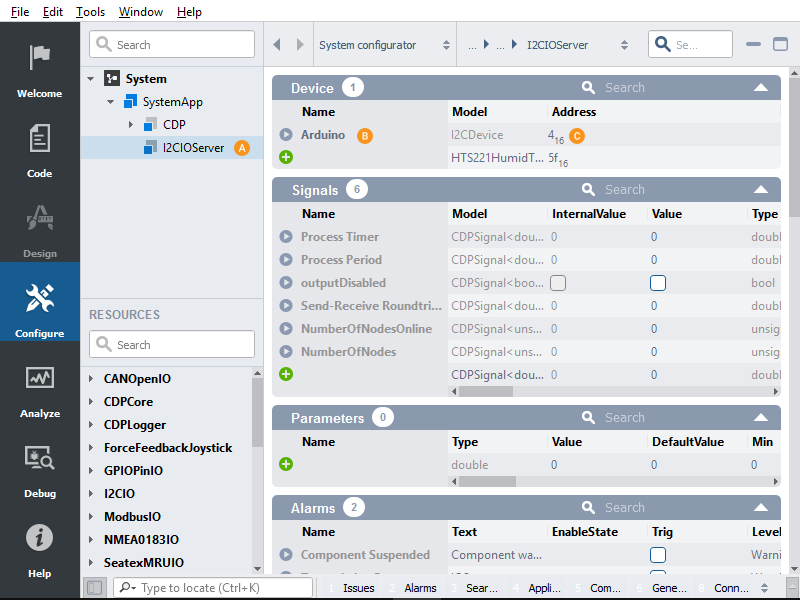
We select the I2CIOServer component.
Then we enter a name and select I2CDevice from the "Model" dropdown.
We then type in the device's I2C address.
Note: We will specify this same address in the Arduino code later.
Adding the I2CRegisterWrite
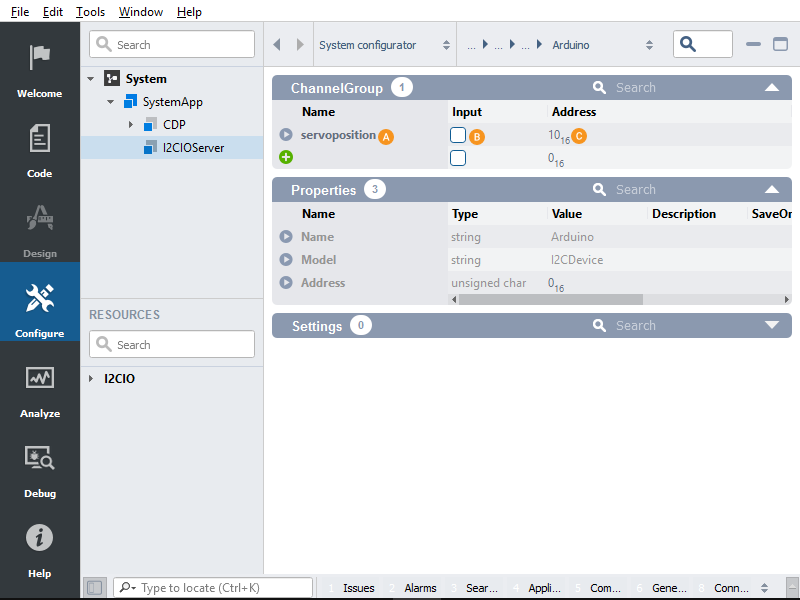
We type in a name for our channel group.
We don't need to change the hidden Input property
We type in an address for our channel.
Note: In the Arduino code, we will handle these addresses with a simple switch case. The raw I2C data that will be transmitted to the Arduino will be "channel address" one byte, followed by the data in the channel.
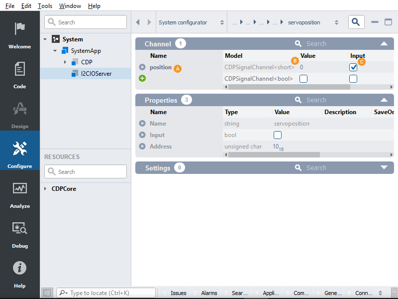
Setting up the data we will transmit
We type in a name for our data.
We select a datatype "Model".
Note: If the data is larger than 1 byte in size then it will be split into several writes, the bytes will be sent in the order "least significant first". In the Arduino code, we will have to read in the data one byte at a time. The "short" type in this case will use 16 bits i.e. 2 bytes.
The input box should be pre-ticked because we wish to input data into this SignalChannel in RegisterWrite operation.
Setting up our Arduino as an I2C Slave
Note: One important thing to remember is that if you wish the Arduino to be the I2C Master then you would need a level converter for the logic. This is because the Arduino operates using a 5-volt logic level, the Raspberry is only constructed for a 3.3-volt logic level. However, this is not a problem as long as the Raspberry is the Master, because the master sets the voltage and 3.3 is still read correctly by the Arduino.
Here you can see the code sample for the Arduino. You can upload it to your Arduino using the Arduino IDE. The channel address that we use to send from the Raspberry "10" is defined as "POSITION_I2C_ADDRESS". In the handleIncoming function, we use the i2c_channel variable to store the channel address. The "ls" and "ms" are the bytes sent from the Raspberry. We configured the Raspberry to send a 16-bit short, in the Arduino it gets read in one byte at a time (8 -it).
If you decide to use a larger type then you need to handle this. If you decide to expand upon this code then you could handle this in the channel's case inside the switch statement.
#include <Wire.h>

#define POSITION_I2C_ADDRESS 0x10
#define ARDUINO_I2C_ADDRESS 0x04

int position = 0;
int i2c_channel;

void setup() {
  // If an I2C address is not specified then we join as master.
  // We initialize i2c as a slave with 4 as our address.
  Wire.begin(ARDUINO_I2C_ADDRESS);

  // We start the serial communication with a 9600 baud rate.
  // In order to print out our values.
  Serial.begin(9600);

  // We provide callback functions to handle the I2C interrupts
  Wire.onReceive(handleIncoming);
  Wire.onRequest(handleOutgoing);
}

void loop() {
  delay(100);
}

// interrupt callback to handle incoming I2C communication
void handleIncoming(int byteCount){
  i2c_channel = Wire.read();
  int ls = Wire.read();
  int ms = Wire.read();

  switch(i2c_channel){
    case POSITION_I2C_ADDRESS:
      position = (ms << 8) | ls;
      Serial.print(position);
      break;
  }

  // Flush if remaining
  while(Wire.available())
    Wire.read();
}

// We are not going to be sending back any values over I2C
void handleOutgoing(){
}
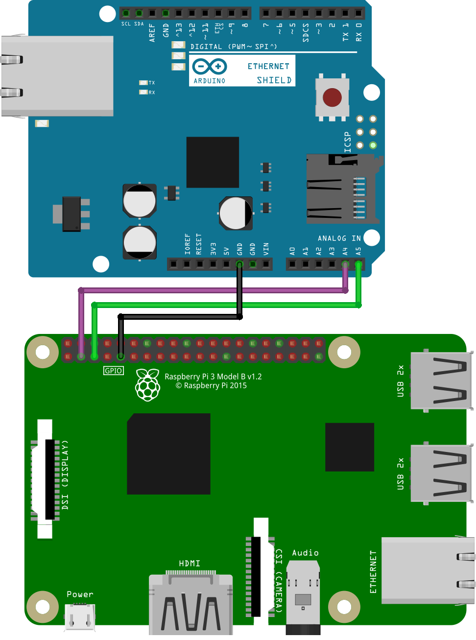
Wiring the Raspberry to the Arduino
We wire the SDA, SCL and ground pins together.
Running the system
With the Arduino and the Raspberry Pi wired up we just need to run the respective programs. We will upload the Arduino sketch using the Arduino IDE. After the sketch has been successfully uploaded we have to open the Serial monitor at 9600 baud rate. Next, we need to deploy and run the CDP System on the Raspberry Pi. When everything is running we can connect to the system and set the position variable in configure mode. The variable should then get sent to the Arduino over I2C and the ArduinoIDE's Serial monitor should output the new value.
Get started with CDP Studio today
Let us help you take your great ideas and turn them into the products your customer will love.