I2C I/O Manual
Introduction
This manual describes how to set up and use I2C I/O in CDP Studio, the independent automation software for open PC-based real-time distributed control systems. In addition, there are some pre-made models and recipes for devices that are typically found in the Raspberry Pi’s.
Note: As only embedded Linux targets have I2C bus there is no Windows support for I2CIOServer. On Windows, the I2CIOServer starts but performs no IO operations.
General purpose models: I2C I/O Server, I2C I/O Device, Reading Writing and Data on I/O Device.
Device-specific models (e.g. Raspberry Pi SenseHat): Accelerometer/Gyroscope, Magnetometer, Pressure/Temperature, Humidity/Temperature.
Pre-made components: Simplified SenseHat component, IOServer for ADS1115 analog-to-digital converter.
I2CIOServer
The I2CIOServer is an IOServer that provides access to the I2C interface. An I2CIOServer enables communication with external devices over the I2C bus.
The I2CIOServer uses an adapter for reading and writing to the I2C bus which is essentially a file specified by Adapter. An I2CIOServer contains a number of I2CDevices.
Properties
The I2CIOServer contains the following properties:
| Property | Description |
|---|---|
| Adapter | Filename of the adapter. Adapters are located at /dev/ (e.g. /dev/i2c-1). Note: One can run i2cdetect -l to get the list of available adapters. |
Warning: I2CIOServer has a meaningful implementation on Linux only. On Windows it has just a dummy implementation.
I2C Adapter setup on Linux
Linux targets may need additional setup steps to enable the I2C bus.
For example, on Raspberry Pi with the Raspberry Pi OS one needs to run the Raspberry configuration tool to enable the I2C kernel module. Run:
$ sudo raspi-config
Select Interfacing options. Choose I2C press enter and enter. Move to finish with the tab key.
The second step is to install tools for the I2C bus. Run:
$ sudo apt-get install i2c-tools
It should be possible now to check for the I2C devices on your target. Run:
i2cdetect -l
The command output should list something like:
$ i2c-1 i2c bcm2835 I2C adapter I2C adapter
The i2c-1 is the adapter that needs to be set in I2CIOServer Adapter property with its full system path /dev/i2c-1
I2CDevice
The I2CDevice represents an external device with an I2C interface. An I2CDevice is specified by its address Address. In general, each external device uses one address. Therefore an I2CDevice supports one address only. External devices that use multiple addresses can be represented by multiple I2CDevices - one I2CDevice for each address. The I2CDevice contains a number of DataOperations for device data read and write operations.
Properties
The I2CDevice contains the following properties:
| Property | Description |
|---|---|
| Name | Name of the I2C device. |
| Model | Model of the I2C device. |
| Address | Address of the I2C device. |
Note: I2CDevice supports 7-bit addresses only. 10-bit addresses are not supported.
To list used/occupied addresses for a specified i2cbus, run the following command (for bus 1):
i2cdetect -y 1
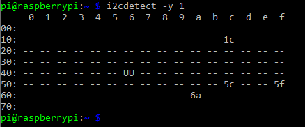
If you e.g. have an I2CIOServer using adapter i2c-1 (bus 1) with the devices LSM9DS1AccelerometerGyroscope, LSM9DS1Magnetometer, LPS25HPressure and HTS221HumidTemp, the command output should list something like this:

LSM9DS1AccelerometerGyroscope, LSM9DS1Magnetometer, LPS25HPressure and HTS221HumidTemp are pre-configured with the addresses 106 (0x6a), 28 (0x1c), 92 (0x5c) and 95 (0x5f), which match the output of occupied addresses. 'UU' usually means that this address is currently in use by a driver.
Reading and Writing Data with DataOperations
The DataOperation represents IO operations for reading or writing a block of contiguous data to/from an external device which may also have a specified starting address (address of the first register when a device has register mapped data) Address. All DataOperations contain a number of CDPSignalChannels which represents the data mapped to the IO operation, in the order the CDPSignalChannels are defined. All CDPSignalChannels in one DataOperation are read or written to the external device using one read or write operation. Therefore input and output CDPSignalChannels can not be mixed within one DataOperation. DataOperation is itself a Read or Write from/to the device.
When DataOperation cumulative data size is larger than 1 byte, block read or write is used. I2C block reads therefore need to auto-increment the address internally. This behavior depends on the exact device (LSM9DS1 discussed in the configuration example has a special configuration bit CTRL_REG8 (0x22) IF_ADD_INC that defaults to "1" that enables this automatically. Some devices require the MSb of the register address to be "1" for address auto increment to occur during block reads. The device data sheet needs to be consulted for specific configuration needs.
I2CRawWrite and I2CRegisterWrite DataOperations are written once on startup and then only on data changes that occur in the Channels. This allows I2C device control registers or configuration word to be configured to desired values during I2CIOServer startup or changed during runtime without excessive load to the bus.
I2CRawRead and I2CRegisterRead are read always at the I2CIOServer configured fs frequency.
Note: Although eight consecutive CDPSignalChannels of type bool make up one byte of data it is the user's responsibility to set the number (Nr='0' to Nr='7') of each CDPSignalChannel.
Properties
The DataOperations based on the I2CDeviceOperation models contain the following properties:
| Property | Description |
|---|---|
| Name | Name of the I2CDeviceOperation. |
| Model | Model name of the operation in DataOperation section |
| Address | Starting address of the block of contiguous registers of the I2CReadRegister and I2CWriteRegister operations. |
| Input | Hidden Internal property specifies whether the DataOperation is input or output. If the property is true, then the values are read from the external device; otherwise the values are written to the external device. |
| RawData | Hidden Internal property specifies whether the DataOperation should use the Address as the first written byte for any data access (this is set false for the Register read/write operations and true for raw data operations.) |
Linux i2cdump Command
The i2cdump command makes it possible to examine I2C register contents. The command
i2cdump -y 1 0x5f
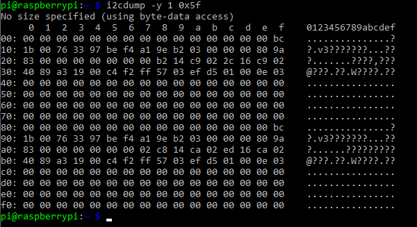
would list the register contents for bus 1 at address 0x5f, which corresponds to HTS221HumidTemp mentioned earlier. The command output should list something like this:

One of the ChannelGroups configured in HTS221HumidTemp is Calibration, with start-address 176 (0xb0). Calibration is by default hidden. To make it visible again, See filter help. When comparing the first channel values in Calibration (when Studio is connected), we have matching values (0x40=64, 0x89=137, 0xa3=163, 0x19=25):

LSM9DS1AccelerometerGyroscope
The LSM9DS1AccelerometerGyroscope provides accelerometer and gyroscope data of STMicroelectronics LSM9DS1 device.
Channels
The LSM9DS1AccelerometerGyroscope contains the following Channels (configuration Channels are not shown, to make them visible in Studio, See filter help.):
| Channel | Description |
|---|---|
| AngularRate.AngularRateX | Angular rate X component in degrees per second (dps). The default range is -245dps...245dps. |
| AngularRate.AngularRateY | Angular rate Y component in degrees per second (dps). The default range is -245dps...245dps. |
| AngularRate.AngularRateZ | Angular rate Z component in degrees per second (dps). The default range is -245dps...245dps. |
| Acceleration.AccelerationX | Acceleration X component in multiples of g-force (g). The default range is -2g...2g. |
| Acceleration.AccelerationY | Acceleration Y component in multiples of g-force (g). The default range is -2g...2g. |
| Acceleration.AccelerationZ | Acceleration Z component in multiples of g-force (g). The default range is -2g...2g. |
Configuration Channels are not described.
LSM9DS1Magnetometer
The LSM9DS1Magnetometer provides magnetometer data of STMicroelectronics LSM9DS1 device.
Channels
The LSM9DS1Magnetometer contains the following Channels (configuration Channels are not shown, to make them visible in Studio, See filter help.):
| Channel | Description |
|---|---|
| MagneticField.MagneticFieldX | Magnetic field X component in gauss (G). The default range is -4G...4G. |
| MagneticField.MagneticFieldY | Magnetic field Y component in gauss (G). The default range is -4G...4G. |
| MagneticField.MagneticFieldZ | Magnetic field Z component in gauss (G). The default range is -4G...4G. |
LPS25HPressure
The LPS25HPressure provides pressure data of STMicroelectronics LPS25H device (it also provides temperature data). The device also has an "AutoZero" mode enabled from Control2.AutoZeroEnable that samples the current pressure and provides a differential to that as Pressure.CurrentValue. Resetting of the AutoZero function is done through cycling Control1.ResetAutoZero bit.
Channels
The LPS25HPressure contains the following Channels (configuration and control Channels are not shown, to make them visible in Studio, See filter help.):
| Channel | Description |
|---|---|
| Pressure.CurrentValue | Absolute pressure measured in hectopascal (hPa). The device range is 260hPa to 1260hPa. |
| Temperature.CurrentValue | Temperature measured in degree Celsius (°C). The device range is -30°C to +105°C. |
HTS221HumidTemp
The HTS221HumidTemp provides humidity and temperature data of STMicroelectronics HTS221 device.
Channels
The HTS221HumidTemp contains the following Channels (configuration and control Channels are not shown, to make them visible in Studio, See filter help.):
| Channel | Description |
|---|---|
| Humidity.CurrentValue | Relative humidity measured in percent (%). The device range is 20% to 80%. |
| Temperature.CurrentValue | Temperature measured in degree Celsius (°C). The device range is +15°C to +40°C. |
SenseHAT
Under I2CIO in Resources, you will find a recipe called SenseHAT. This is a recipe that is compatible with the Raspberry Pi Sense HAT. If you add SenseHAT to your application, you will get a CDPComponent containing relevant Sense HAT signals and a pre-configured I2CIOServer with Sense HAT devices (LSM9DS1AccelerometerGyroscope, LSM9DS1Magnetometer, LPS25HPressure and HTS221HumidTemp).
Note: If your application has multiple I2CIOServers, make sure that each of them accesses different adapters. For instance, the first can access '/dev/i2c-1' and the second can access '/dev/i2c-2'.
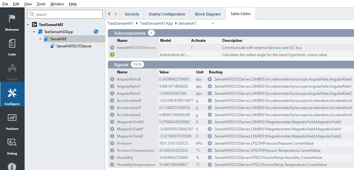
When running your application, it should look something like this:

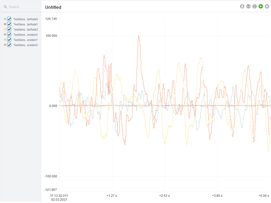
If you add the AngularRateX/Y/Z and AccelarationX/Y/Z to a plot, and at the same time move your Raspberry Pi, you should get a plot similar to this:

ADS1115 IOServer
The ADS1115 IOServer provides access to the I2C interface to communicate with ADS1115 analog-to-digital converter.
The IOServer uses an adapter for reading and writing to the I2C bus which is essentially a file specified by Adapter. For each ADS1115 input there is a signal providing the values for easy access and a property to enable/disable inputs. Data rate and gain are configurable by properties.
Signals
The ADS1115 IOServer contains the following signals:
| Signal | Description |
|---|---|
| A0 | Voltage difference between A0 and GND |
| A1 | Voltage difference between A1 and GND |
| A2 | Voltage difference between A2 and GND |
| A3 | Voltage difference between A3 and GND |
| A0A1 | Voltage difference between A0 and A1 |
| A0A3 | Voltage difference between A0 and A3 |
| A1A3 | Voltage difference between A1 and A3 |
| A2A3 | Voltage difference between A2 and A3 |
Properties
The ADS1115 IOServer contains the following properties:
| Property | Description |
|---|---|
| Adapter | Filename of the adapter. Adapters are located at /dev/ (e.g. /dev/i2c-1). Note: One can run i2cdetect -l to get the list of available adapters. |
| DataRate | Controls the data rate setting. Valid values are 8SPS, 16SPS, 32SPS, 64SPS, 128SPS (default), 250SPS, 475SPS and 860SPS |
| Gain | Programmable gain amplifier. Note that in no event should more than VDD + 0.3V be applied to this device. Valid values are ±6.144V, ±4.096V, ±2.048V (default), ±1.024V, ±0.512V and ±0.256V. |
| EnableA0 | Enables reading input into A0 signal. Disable to improve performance |
| EnableA1 | Enables reading input into A1 signal. Disable to improve performance |
| EnableA2 | Enables reading input into A2 signal. Disable to improve performance |
| EnableA3 | Enables reading input into A3 signal. Disable to improve performance |
| EnableA0A1 | Enables reading input into A0A1 signal. Disable to improve performance |
| EnableA0A3 | Enables reading input into A0A3 signal. Disable to improve performance |
| EnableA1A3 | Enables reading input into A1A3 signal. Disable to improve performance |
| EnableA2A3 | Enables reading input into A2A3 signal. Disable to improve performance |
Warning: I2CIOServer has a meaningful implementation on Linux only. On Windows, it has just a dummy implementation.
Note: Comparator functionality of ADS1115 is not supported.
Get started with CDP Studio today
Let us help you take your great ideas and turn them into the products your customer will love.