PLCnext I/O Configuration Example
Introduction
This example demonstrates usage of PLCnext I/O. The PLCnextIO component is able to read values from the CDPIO PLCnext extension app to update configured CDP channels (signals) with values to and from CDP.
Note: Make sure the prerequisites are fulfilled before reading further.
Set up the I/O
This example requires that the following is set up:
- An AXC F 2152
- An AXL-F-AI2-AO2-1H (AI2 + AO2) I/O module
- Power and ground connection to the I/O and the I/O module
- Ethernet connection to the host computer
- Connect AXL-F-AI2-AO2-1H 00 with AXL-F-AI2-AO2-1H 02
- Connect AXL-F-AI2-AO2-1H 10 with AXL-F-AI2-AO2-1H 22
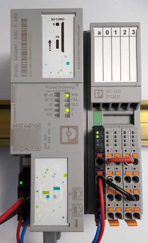
The above image shows how the AXC F 2152 is set up for this example.
Set up a Test-system
First we set up a System that the PLCnexIO can be tested in:
Create a system named "PLCnext" with a Console application named PLCnextApp, then select Configure mode. See How to Create a system for more information.
Add a Test Component
In the below steps, we add a component to generate some test-data for our I/O.
- Select the PLCnextApp that resides under PLCnext in the Project tree.
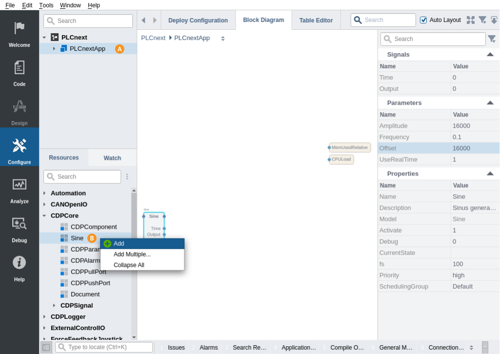
- Select/expand CDPCore in the Resource tree, right-click on Sine and select Add.
- Select the newly added Sine component.
- In the Parameters table, set Amplitude to 16000
- Set Offset to 16000
- Right-click on the Output signal and select Copy Path, as we want to connect this later.
Add a PLCnextIO Component
In the below steps, we add a PLCnextIO component to the system, and add a module to the I/O.
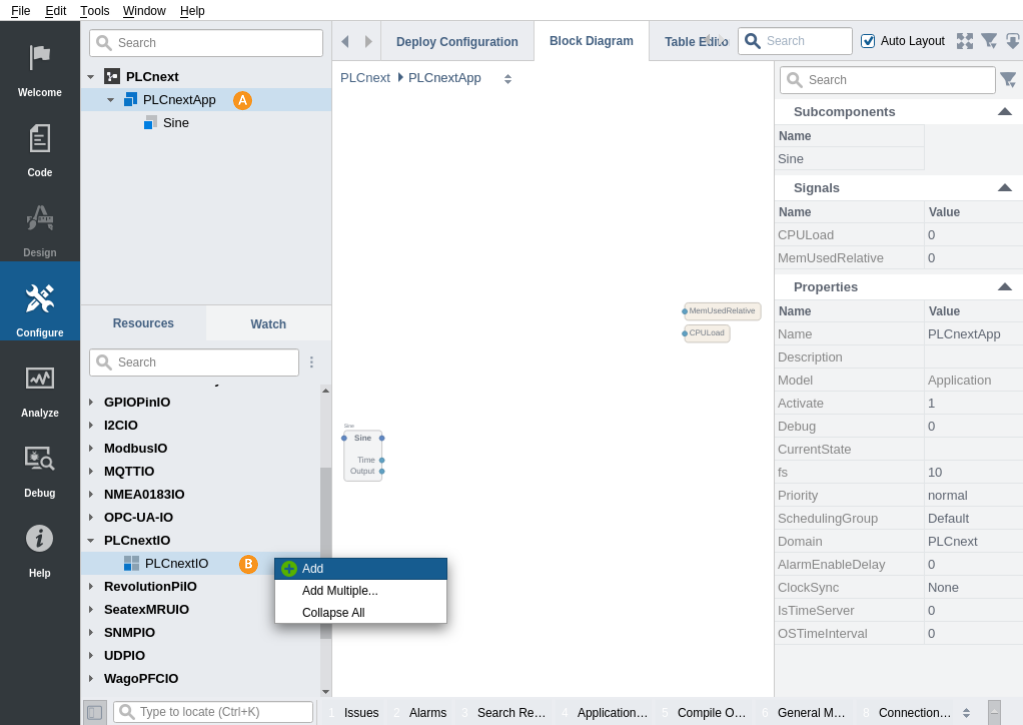
- Select the PLCnextApp that resides under PLCnext in the Project tree.
- Expand PLCnextIO in the Resource tree, right-click on PLCnextIO and select Add.
Add a Module and Configure It
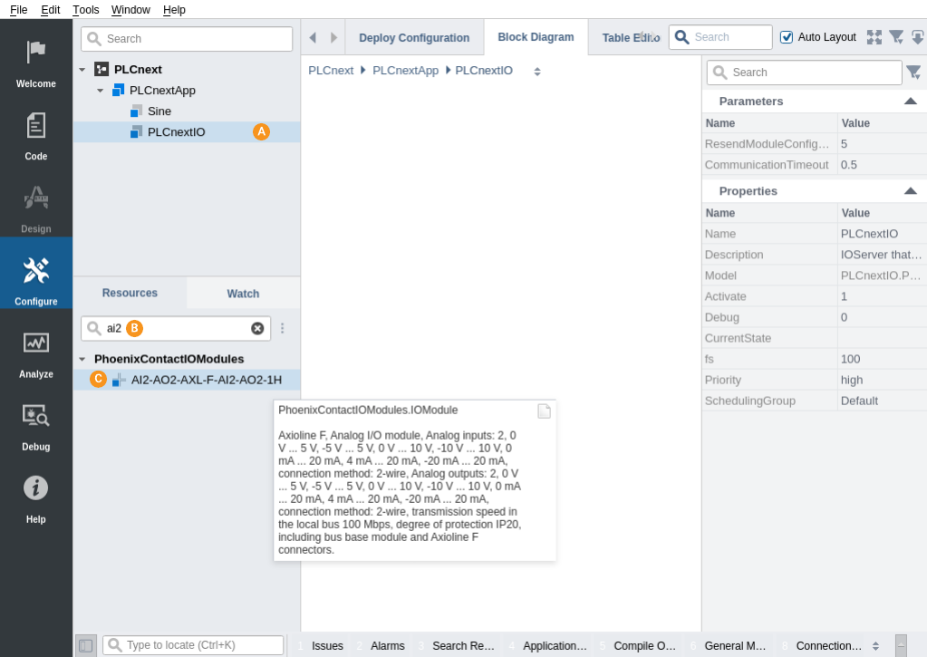
- Select the PLCnextIO in the Project tree.
- In the Resource tree, type in AI2 in the 'Search' field.
- Double-click the 'AXL-F-AI2-AO2-1H' module to add it into the PLCnextIO.
- Double-click PLCnextIO in the Block Diagram to see the added module
- Right-click on the port for AO0 and select Connect From 'PLCnextApp.Sine.Output'
Select Toolkit and Pair
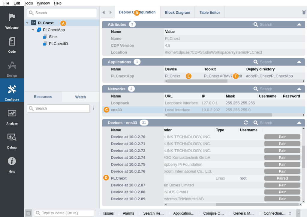
- Select PLCnext in the Project tree.
- Select the Deploy Configuration tab
- In the Networks table, select the network that the physical PLCnext device is on.
- In the Devices table, find the IP-address of the PLCnext device.
- Double-click on the IP-address in Name-column to rename it to PLCnext, then type in root into Username, and select 'Pair'. Enter the password if a dialog pops up.
- In the Applications table, select Device 'PLCnext' and select PLCnext ARMv7 32-bit Toolkit
How to Run the Tutorial
To run the tutorial from CDP Studio, select Configure mode, right-click on the system project and select Run & Connect. See the Running and Connecting to the System tutorial for more information.
Verify That It Works
- Click into PLCnextApp.AXL-F-AI2-AO2-1H.
- Verify that the sine value propagates from the Sine output into AO0 and back in from AI0.
Note: For more information about CDP Technologies partnerships, see Our Partners and for detailed information on Phoenix Contact, see the Phoenix Contact website for more information.
Get started with CDP Studio today
Let us help you take your great ideas and turn them into the products your customer will love.