WagoCC100IO Configuration Example
WagoCC100IO Configuration Example
Note: Make sure that you have performed the first-time setup of the wago cc100 I/O as outlined here.
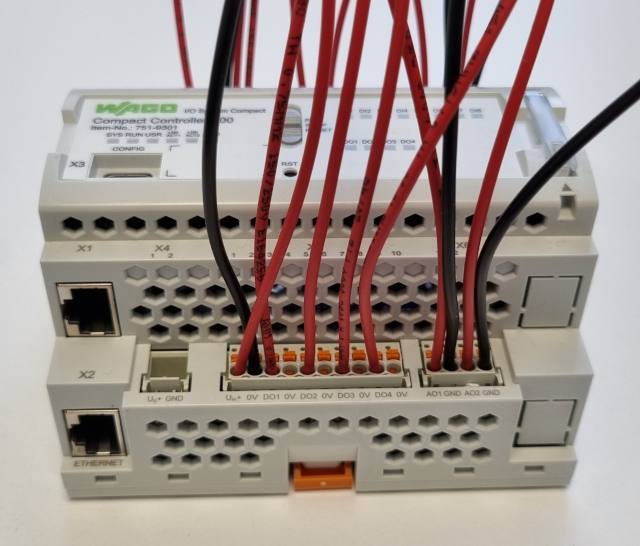
The following example will show a simple way to test a WagoCC100IO by looping Digital outputs to inputs and by looping Analog outputs to inputs.
Physical connection

Make sure to connect the Inputs and Outputs together for the below test to work:
| From | To |
|---|---|
| X12 Uout+ | X5 Uin+ |
| X12 GND | X5 0V |
| X12 DI1 | X5 DO1 |
| X12 DI2 | X5 DO2 |
| X12 DI3 | X5 DO3 |
| X12 DI4 | X5 DO4 |
| X14 AI1 | X6 AO1 |
| X14 GND | X6 GND |
| X14 AI2 | X6 AO2 |
| X14 GND | X6 GND |
Set up a Test-system
First we set up a System that we can test the component in:
Create a system named WagoCC100Demo with a Console application called WagoCC100DemoApp, then select Configure mode. See How to Create a system for more information.
Configure the I/O Server
- Select the WagoCC100DemoApp that resides under WagoCC100Demo in the Project tree.
- In the Resource tree, expand WagoCC100IO and double-click the WagoCC100IO to add it.
Connect the I/O to the Control System
To set a signal out to the I/O, you can connect the Sine generator to a physical output:
- Select the WagoCC100DemoApp in the Project tree.
- From the Resource tree, click into the CDPCore resource and double-click on Sine to add it to the WagoCC100DemoApp
- Select the newly added Sine component. Since the analog output module accepts values between 0 and 10V, we want to make the Sine generate values in that range.
- Set the parameter Value of Amplitude to 5.
- Set the parameter Value of Offset to 5
- Click into the WagoCC100DemoApp in Block Diagram.
- Drag a connection from Sine.Output to WagoCC100IO.AO1
- In the Subcomponents table, rearrange the scheduling-order of WagoCC100IO and Sine so that the Sine is listed first.
Pairing and Setting Up
- Make sure you have performed the first-time setup of the wago cc100 I/O as outlined here.
- Specifically, Pair the Device.
- In the Applications table, select the WagoCC100 device and make sure you select the WAGO ARMv7 32-bit Toolkit, as that is compatible with the WagoCC100 controller.
How to Run the Tutorial
To run the tutorial from CDP Studio, select Configure mode, right-click on the system project and select Run & Connect. See the Running and Connecting to the System tutorial for more information.
Verifying That It Works
- Click on Analyze mode.
- Add the AO1, AI1 and DI1 signals in WagoCC100IO to the graph.
- Add DO1 to Watch.
- Autoscale / zoom the graph to view the signals.
- Now monitor the AO1 and AI1 in analyze mode. Here you can see the value changes, and the propagation delay between value write and value read.
- In the watch window, change DO1 and watch how DI1 changes accordingly.
- Similarly, verify that the other looped outputs change the inputs they are looped to by setting values into the output channels.
Get started with CDP Studio today
Let us help you take your great ideas and turn them into the products your customer will love.