Implementing a Custom Protocol
Introduction
The purpose of this example is to demonstrate how to create a custom IOServer to perform variable speed control of a device by using a custom serial protocol.
This example demonstrates:
- How to create a simple custom IOServer in C++ with Online and Offline state handling
- How to read and write data using the Transport class
- How to add a SerialTransport element
- How to scale between engineering values and hardware values
Note: This example requires either a serial-port, or a USB-to-Serial adapter, similar to the one in the picture below.
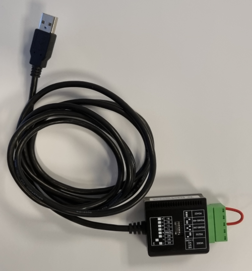
ExSys EX-1309-T RS-232/422/485 serial adapter
Since we don't have an actual device that responds to the speed commands, we connect the send and receive pins together in a loop so that anything we send out is returned to us, making it seem like we communicate with a device with instantaneous response time.
Note: Before running the example, make sure to connect the looped serial adapter, and configure the CustomIO component SerialTransport ComPort property.
How to Run the Example
To run the example from CDP Studio, open Welcome mode and find it under Examples. Next, in Configure mode right-click on the library project and select Build, then right-click on the system project and select Run & Connect. See the Running the Example Project tutorial for more information.
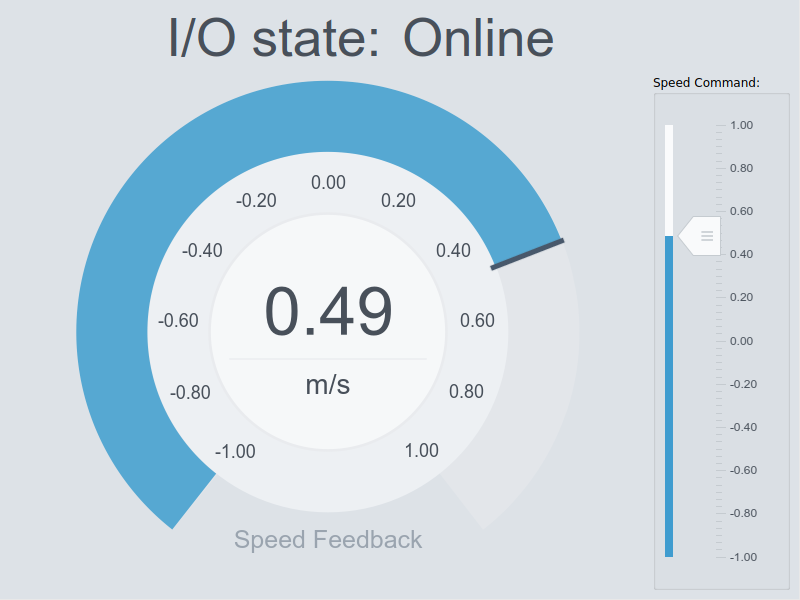
There are two applications; one that contains the CustomIO that communicates on the serial port, and one that contains a GUI. The GUI application sets the Speed command from a Slider widget, and visualizes the Feedback in a Speedometer. It also shows the serial IOServer state:
By setting the Debug property in the CustomIO component to 1, the application will print out messages about what it is doing. This can be useful to help investigate errors without having to run the application in a debugger. To turn off the messages, set the Debug property to 0.
Project Overview
The example has a CustomIOLib library that contains the CustomIO IOServer that communicates with an imaginary serial device. The serial device takes in a signed 16 bit speed command ranging from -32768 (max negative/reverse speed) to 32767 (max positive speed). It returns a signed 16 bit value for the currently measured speed (which has the same range as the speed command). It implements the following protocol:
Speed Command:
| Byte address | Content | Description |
|---|---|---|
| 0 | 0xff | First header byte |
| 1 | 0x99 | Second header byte |
| 2 | <any> | First speed-byte of wanted speed (Least significant speed byte as taken from a signed 16 bit value) |
| 3 | <any> | Last speed-byte of wanted speed (Most significant speed byte as taken from a signed 16 bit value) |
Speed Response:
| Byte address | Content | Description |
|---|---|---|
| 0 | 0xff | First header byte |
| 1 | 0x99 | Second header byte |
| 2 | <any> | First speed-byte of actual speed (Least significant speed byte as taken from a signed 16 bit value) |
| 3 | <any> | Last speed-byte of actual speed (Most significant speed byte as taken from a signed 16 bit value) |
The wanted Speed is put into the Speed Command and sent periodically based on the configured component fs property, and then the response is read and the speed Feedback is updated. As long as a good response is read back, the IOServer is in Online state, if not it is in Offline state.
Note: Even if the CustomIO is in Offline state, it will still try to send data out. If it gets expected data back, NumberOfNodesOnline() is updated and the IOServer enters Online state.
CustomIO Implementation
The CustomIO IOServer code can be inspected by going into Code mode and looking at the CustomIO.h and CustomIO.cpp files. The CustomIO model can be inspected in Configure mode.
Below is a step-by-step guide to make the component yourself or to get a better understanding of the existing code.
Start by adding a Custom IOServer to a library by using the Add New... -> Custom IOServer wizard. Name it CustomIO. It should then be modified in Configure mode:
- Add a CDPSignal<short> named Speed, and check the Input attribute.
- As we want the UI to show a -1 to 1 value for the Speed and Feedback instead of the -32768 to 32767 range that the hardware wants, we add an Automation -> Scale<double> operator to the Speed signal.
- Add two Automation -> ScalingPoint<double>s to the Scale Operator with the following configuration:
| Name | InValue | OutValue |
|---|---|---|
| ScalingPoint | -1 | -32768 |
| ScalingPoint1 | 1 | 32767 |
- Add CDPSignal<short> named Feedback to CustomIO and make sure the Input attribute is unchecked.
- Add an Automation -> Scale<double> operator to the Feedback signal (we want to show -1 to 1 range on the CDP side)
- Add two Automation -> ScalingPoint<double>s to the Scale Operator with the following scalings:
| Name | InValue | OutValue |
|---|---|---|
| ScalingPoint | -32768 | -1 |
| ScalingPoint1 | 32767 | 1 |
Note: The above scaling will cause an input of -32768 (from the I/O device) to be scaled to -1 and an input of 32767 will be scaled to 1, and anything inbetween will be scaled according to the Interpolation algorithm chosen in the ScalingOperator.
- The IOServer generated by the Custom IOServer wizard has a Transport element that can hold a model based on Transport. The library must be built to make CDP Studio expose it:
- Build the library. The CustomIO component will now have a Transport table that accepts all the available Transport-based Models.
- Add a CDPCore -> SerialTransport into the Transport table, and go into it.
- Here you can set the default properties for the transport as they should appear when a user drags the CustomIO in as a component.
- Set Baudrate to 115200, and Timeout to 0.5
Now go to Code mode and do the following changes:
- Add the ShouldSkip() function:
bool CustomIO::ShouldSkip()
{
    return m_transport->IsError() | Stopped();
}
- Add the IsResponseOK() function:
bool CustomIO::IsResponseOK(unsigned char *response)
{
    return (response[0]==0xff && response[1]==0x99);
}
- Add the RecoverFromError() function:
void CustomIO::RecoverFromError()
{
    char dummy;

    if (DebugLevel(DEBUGLEVEL_NORMAL))
        CDPMessage("%s: Didn't get the expected header [0xff, 0x99] from serial, trying to recover stream...\n",CDPComponent::Name());
    // Empty input buffer
    while(!m_transport->IsError() && m_transport->Read(&dummy,1,0.00001)==1)
        OSAPISleep(0);
}
- Add the ProtocolImplementation() function to handle writing Speed and reading Feedback from the I/O.
This is the function that reads the Speed signal and sends it together with a header on a configured transport. It then waits for a response (within the configured Transport Timeout) and reads the speed Feedback. Inbetween, it writes out status CDPMessages to the Application Output pane, but only if the Debug property is 1 or more. At the end it updates the NumberOfNodesOnline, Feedback, and RoundtripTime signals:
void CustomIO::ProtocolImplementation()
{
    OSAPIMutexLocker locker(GetMemberAccessMutex(),"Main thread member access"); // automatic unlock when object is destroyed
    short temp_speed = Speed;
    locker.Release();

    const unsigned int telegram_length = 4;
    unsigned char telegram_to_send[telegram_length] = {0xff,0x99,0,0}; // pre-initialized array with 4 bytes
    telegram_to_send[2] = temp_speed&0x00ff;      // get the low byte from speed signal and put into telegram array at position 2
    telegram_to_send[3] = (temp_speed&0xff00)>>8; // get the high byte from the speed signa land put into telegram array at position 3

    short returned_speed = 0;
    CDPTimer roundtriptime_measurement;
    roundtriptime_measurement.Start();

    if (!ShouldSkip() && m_transport->Write(reinterpret_cast<const char*>(telegram_to_send),telegram_length)==telegram_length)
    {
        if(DebugLevel(DEBUGLEVEL_NORMAL))
            CDPMessage("%s: Wrote %u bytes!\n",CDPComponent::Name(),telegram_length);
        unsigned char response_buffer[telegram_length]={0,0,0,0};
        if (!ShouldSkip() && m_transport->Read(reinterpret_cast<char*>(response_buffer),telegram_length)==telegram_length)
        {
            if(DebugLevel(DEBUGLEVEL_NORMAL))
                CDPMessage("%s: Read %u bytes into response buffer!\n",CDPComponent::Name(),telegram_length);
            if (!ShouldSkip() && IsResponseOK(response_buffer))
            {
                returned_speed = (response_buffer[2]) | (response_buffer[3]<<8);
                if(DebugLevel(DEBUGLEVEL_NORMAL))
                    CDPMessage("%s: SUCCESS: Got speed response %d!\n",CDPComponent::Name(),returned_speed);
                m_lastUpdateTime = CDPTime::GetGlobalTime();
            }
            else
                RecoverFromError();
        }
        else if(DebugLevel(DEBUGLEVEL_NORMAL))
            CDPMessage("%s: Error reading response within timeout\n",CDPComponent::Name());
    }
    else if(DebugLevel(DEBUGLEVEL_NORMAL))
        CDPMessage("%s: Write failed writing 4 bytes\n",CDPComponent::Name());

    locker.Lock();
    m_SendReceiveRoundtrip.SetDouble(roundtriptime_measurement.TimeElapsed());
    Feedback = returned_speed;
    locker.Release();
}
To use the CustomIO component in an application, build the library, then from the Resource tree add a CustomIOLib -> CustomIO component into the application. Click into it and make sure to configure the SerialTransport -> ComPort inside it. Run the system and manipulate Speed in the GUI app and observe the Feedback. By removing and reinserting the physical connection between RX and TX on the serial cable, you can observe that the IOServer goes to Offline state and then later recovers and goes to Online state.
Note: The Speed and Feedback signals have CDPOperators to perform scaling/value conversion between what the CDP side expects and what the hardware expects. When connecting the Speed signal from a UI, make sure to route to the InternalValue of the signal. By Routing the UI widget to the InternalValue, you make sure that the widget sets and reads the signal value before the CDPOperators are executed. For a more detailed explanation, see CDP Operator Usage In CDP Signals.
Expanding the CustomIO
Since the CustomIO uses a generic Transport class, it can easily be adapted to use UDP or TCP instead of serial. To do this:
- Select the CustomIO model in the CustomIOLib library
- Delete the SerialTransport from the Transport table
- From the CDPCore resource in the Resource tree, add a UDPTransport or TCPTransport to the Transport table
The CustomIO can also be expanded with CDPNodes to expose custom data, or to handle creating dynamic signals based on what is in the component configuration. For more information about this, see the IOServer documentation.
Get started with CDP Studio today
Let us help you take your great ideas and turn them into the products your customer will love.