Siemens Simatic Modbus Slave Tutorial
Tutorial Overview
In this tutorial, you will learn how to use the Siemens Step7 software to set up a Siemens S7 1511 PLC with a Modbus Slave and how to use CDP Studio to set up a Modbus Master to communicate with the PLC. The CDP Studio application will optionally be deployed and run on a Siemens S7 TM MFP Linux controller (alternatively, it is just run from a PC) connected via Ethernet to the Siemens S7 1511 controller.
Prerequisites
- A Siemens S7 series PLC with Modbus support
- Siemens Step 7 (version 19 is used in this tutorial)
- A PC running CDP Studio
- [optional] Siemens S7 TM MFP Industrial Linux Controller
Setting up the Siemens Simatic Modbus Slave
- To set up the Siemens S7 software, it must first be downloaded from the TIA portal. The version used in this tutorial is STEP 7 V19.
- After installing it, you must create a new project, and add the CPU 1511-1 PN, and add the devices that are used into the device view from the hardware catalog. We have added a PSU, a 1511 PLC and a TM MFP module:
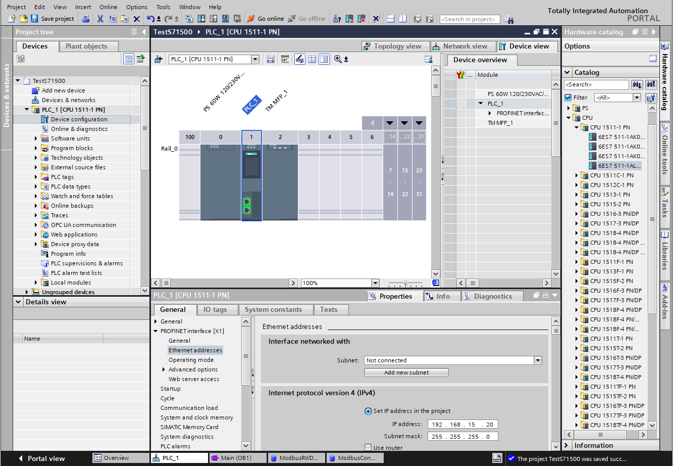
You can set up the ethernet ip address directly on the device, but it is also possible to set it from Step 7 or from DHCP. Doubleclick the PLC and verify that ‘Ethernet Addresses’ is set correctly.
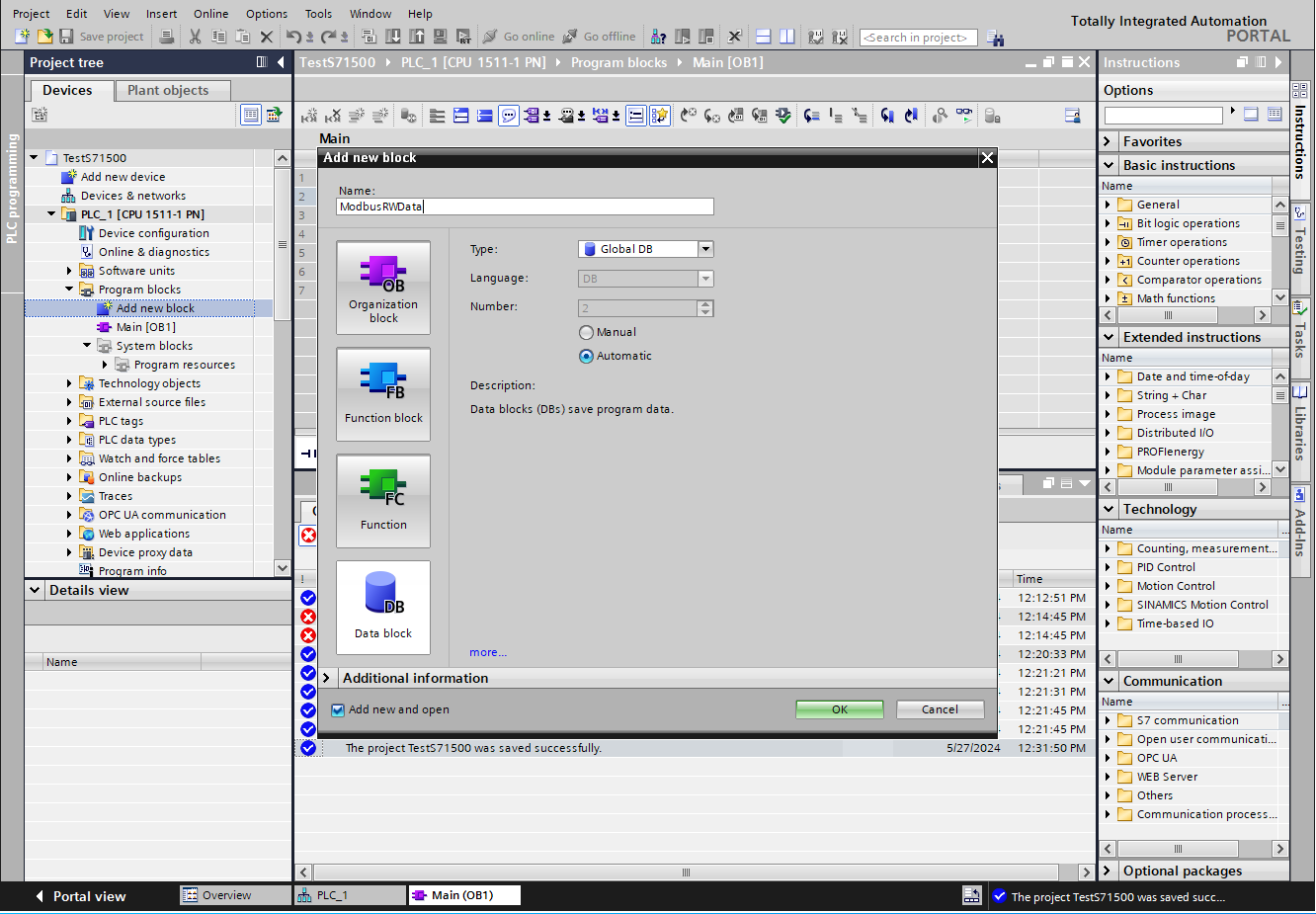
- In program blocks, ‘Add new block' 'Data block’, and call it ModbusRWData:
- Select the block and add 20 WORDs of data. Make sure to separate inputs and outputs into separate areas so that all inputs can be accessed as one block, and all outputs can be accessed as one block:
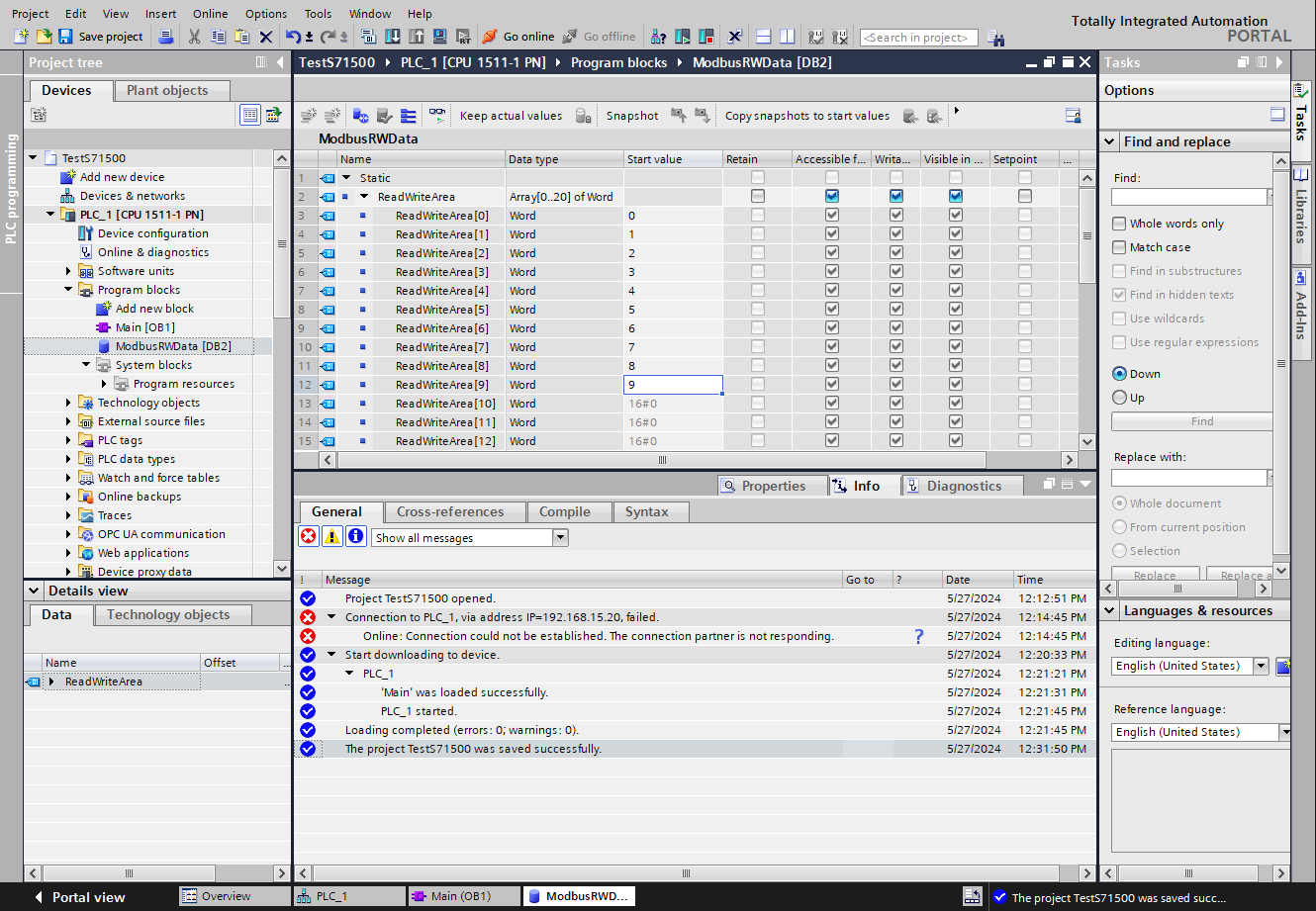
Note: The data does not have to be an array of words; individual types can be used. The CDP Studio Modbus Master will by default read data from (16 bit register) offset 0 in this block, and write data starting at (16 bit register) offset 10. Make sure to change the Modbus Master ReadAddress and / or WriteAddress if you change the amount and/or layout of this data. If the CDP Studio Modbus Master only reads or only writes data, make sure to change the FunctionCode in the CDP Studio modbus I/O to either 'ReadHoldingRegisters' or 'WriteMultipleRegisters'.
- Go to Program blocks Main , and add an MB_SERVER from the Instructions Communications pane into the 'Network 1' rung:
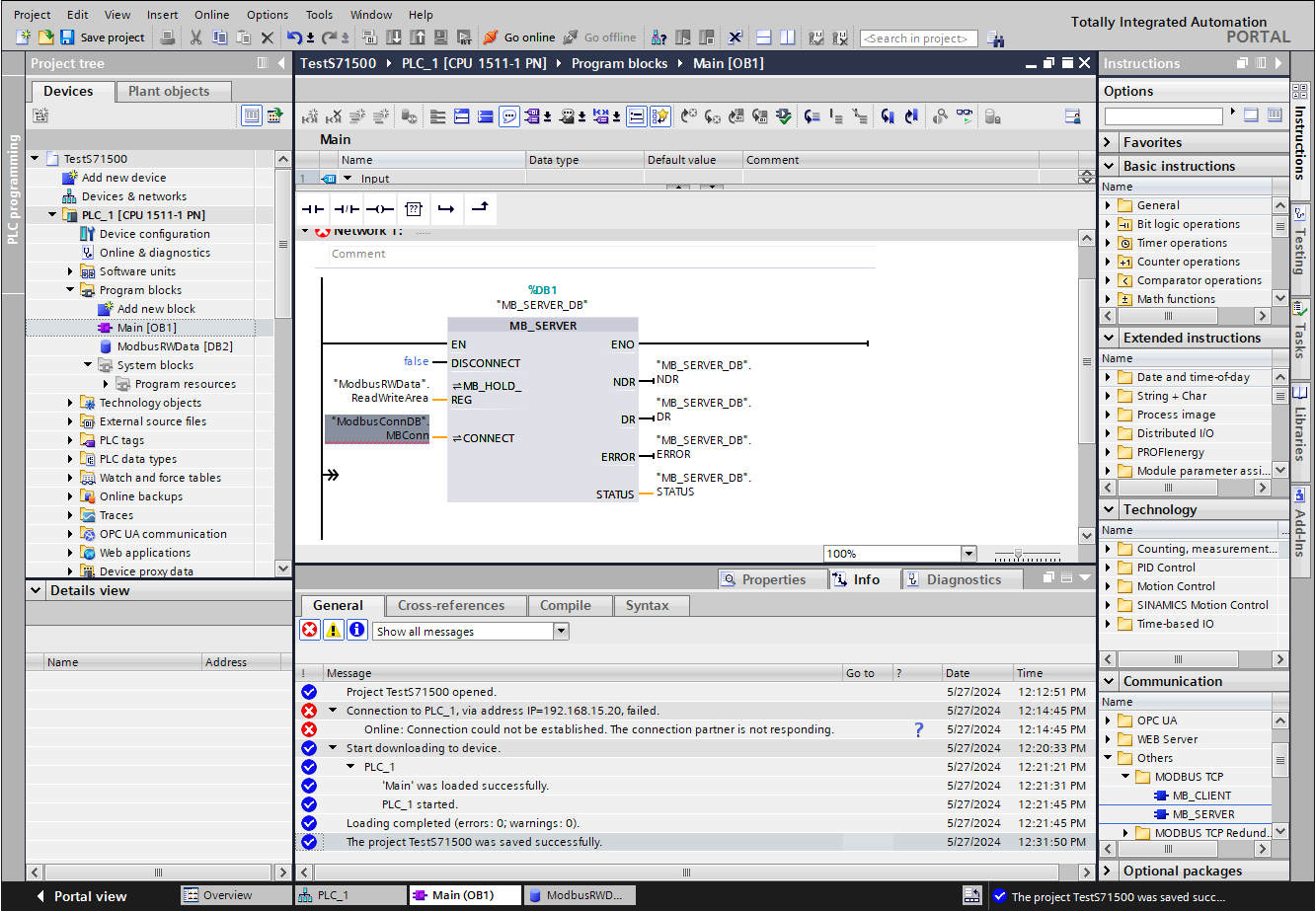
- In the Main program block, make sure to set MB_SERVER.DISCONNECT to false.
- Set MB_SERVER.MB_HOLD_REG to ModbusRWData.ReadWriteArea (or whatever you called it in Step 1. Just make sure to point it to the first data in the db block).
- Connect NDR, DR, ERROR and STATUS to MB_SERVER_DB.NDR etc, see the image above.
- In Program blocks, ‘add new block' ‘Data block’ , call it ModbusConnDB. Add a variable called MBConn of type TCON_IP_v4 (You have to type 'TCON_IP_v4' into the 'Data type' field, press enter and then expand it):
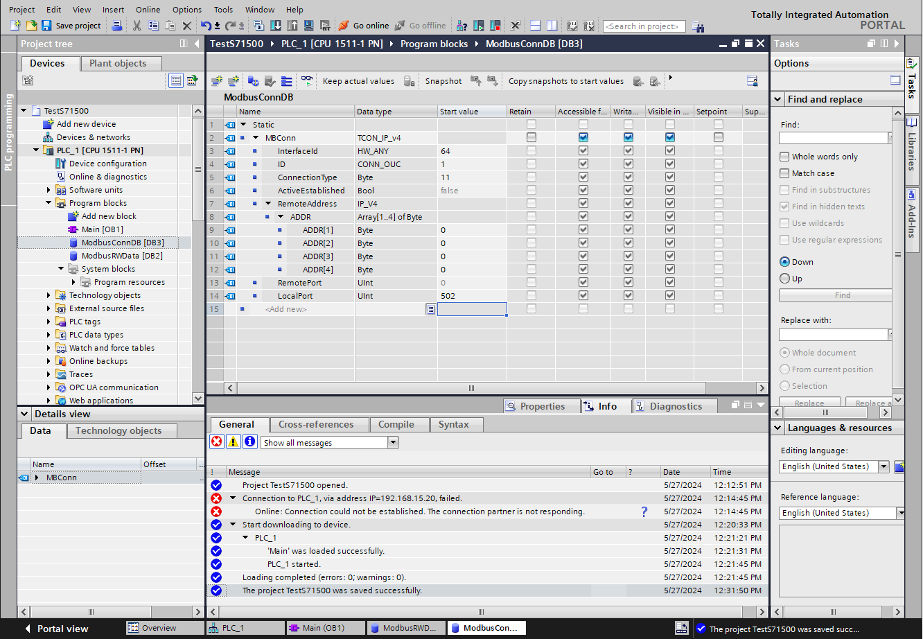
- The interface ID must match the ID that you can find in PLC_1 'System constants':
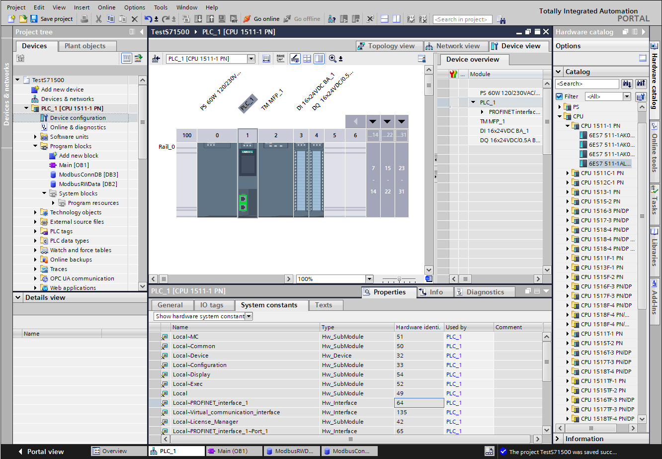
For this PLC system it is ‘64’
- Set ID to 1
- Set ConnectionType to 11
- Set LocalPort to 502.
- RemoteAddress can be set to the ip address of the IPC if you want it restricted to only that, or leave it as 0.0.0.0 to allow all connections.
- In Program blocks Main, make sure to select MB_SERVER_DB.CONNECT and connect that to ModbusConnDB.MBConn
- To verify that we can send and receive data, we want to loop the write value to the read value in the PLC. A simple way to do this is to add a 'move' block as shown in the picture below:

- Compile the program
- Download to Device
- Select 'Start module'
- Click Finish.
The PLC Should now be running with the Modbus Slave waiting for a master to connect.
Setting up the CDP Studio Modbus Master
In CDP Studio, we now want to set up the Modbus Master that shall communicate with the Siemens S7 Modbus Slave. Start in Welcome mode by creating a system named SiemensS7Test, with a Console application named SiemensS7TestApp, then select Configure mode. See How to Create a system for more information on how to create a system.
Adding a Sine Component to Generate a Test Signal
- Select the SimensS7TestApp that resides under SiemensS7Test in the Project tree
- In the Resource tree, expand the CDPCore resource and double-click on Sine to add a Sine component.
Adding a Modbus Master Component
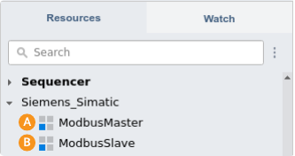
- In the Resource tree, select the SimensS7TestApp, then select the Siemens_Simatic resource
- Double-click on ModbusMaster to add it:
- Double-click the newly added ModbusMaster in the Block Diagram to navigate into it
- Set the fs property to 100. This is how many times per second it will send the Modbus Master requests.
- Double-click the NetworkTransport to configure the transport
- In the Transport table, set RemoteIP to the IP address of the Siemens S7 PLC (192.168.15.20 in our example)
- In the Project tree, select the ModbusMaster
- DoubleClick the IO packet to enter into it.
Note: The IO packet is preset with FunctionCode ReadWriteMultipleRegisters, ReadAddress 0 and WriteAddress 10. If this does not match what you set up in the PLC, change it here. Be aware that the addresses are typed in as hexadecimal numbers.
- Select the IO packet, then from the Resource tree CDPCore resource, double-click to add an IOModule.
- Double-click the added IOModule in the Block Diagram to go into it.
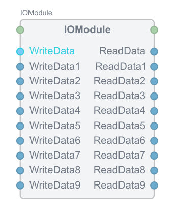
- From the Resource tree CDPCore module, right-click CDPSignalChannel<short> Add Multiple..., and in the dialog that pops up set Base name to ReadData and Count to 10 and click OK.
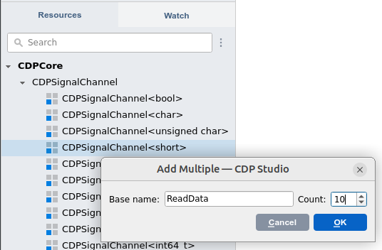
- Repeat the last step and add 10 more items of type CDPSignalChannel<short>, named WriteData
- To inform CDP Studio that all the WriteData are inputs to the IOModule , click the Table Editor, select WriteData and hold down the SHIFT key and select WriteData9, then click Input. All the WriteData Channels should now have Input checked.
Note: The input and output direction in I/O Servers can be confusing. It might help to think about the I/O as a block in Block Diagram:
The IOModule takes the data to write as input and writes them out to the PLC inside the block. The IOModule also reads data from the PLC inside the block, and updates all the ReadData outputs.
- The IOModule should now look like this in the Block Diagram tab:
Connect the Sine to WriteData
- Select the Block Diagram tab
- In the Project tree, select the SiemensS7TestApp.Sine component
- Right-click Output and select Copy Path
- In the Project tree, select the ModbusMaster and double-click the IO packet.
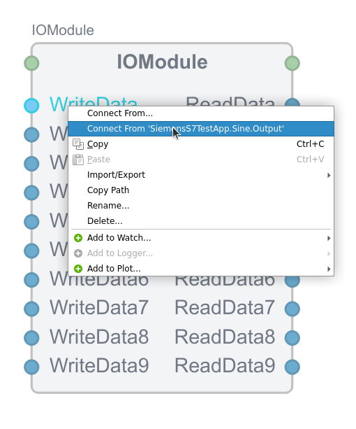
- Right-click WriteData, and select Connect From 'SiemensS7TestApp.Sine.Output':
Change Output Scaling
The SiemensS7TestApp.Sine.Output is of type double and has a range from -1 to 1. We have set up the ModbusMaster with (integer) values of type short, which has a range from -32768 to 32767. If we pass the Sine values directly to the ModbusMaster, the floating-point values from the Sine will be implicitly converted to integer values, and only the values -1,0 and 1 will be passed to the Siemens PLC. We can correct this issue by adding a Scaling operator to the SiemensS7TestApp.ModbusMaster.IO.IOModule.WriteData. It can be done like this:
- Navigate into SiemensS7TestApp.ModbusMaster.IO.IOModule.WriteData.
- From the Resource tree Automation resource, add a Scale<double> operator
- Navigate into the added Scale operator
- From the Resource tree Automation resource, right-click ScalingPoint<double> and Add Multiple with Base name SP0 and set Count to 2.
- Click the Table Editor, and set up the scalingpoints as shown in the image below:
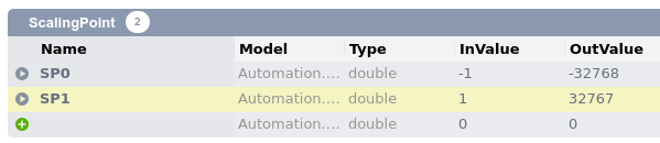
- Due to the routing that we set in the previous section, the Sine.Output value will now go into the WriteData value, pass through the scaling operator, and be scaled between -32768 and 32767, producing values that fit nicely into the Word variable set up in the Siemens PLC.
Set up the Siemens TM MFP
Note: If you don't have a Siemens TM MFP, or if you want to run the application on your Local PC, you can skip down to the section called Deploy and Analyze.
If this is the first time you set up the Siemens TM MFP, or you have not set up a password for it yet, you must first set it up with a new password:
- Open a Terminal
- Assuming the Siemens TM MFP has the default 192.168.15.19 IP address, type in:
ssh mfp@192.168.15.19 - then press ENTER and type in 'mfp' as password. When asked to change the password, change it to a strong password. Make sure you remember the password, you will neeed to re-type it below. If you experience problems, make sure to consult the Siemens documentation on how to log in to the TM MFP device.
Pair the Siemens TM MFP
- In CDP Studio Deploy Configuration, scan the 192.168.15.* network, and select Device at 192.168.15.19
- Change the name to SiemensMFP
- Click in the Username column, and set that to mfp
- Click the Pair button.
- When asked for the password, type in the password for the Siemens TM MFP and then click OK.
- In the Applications table, locate the SiemensS7TestApp.
- Select the Device column and change it to SiemensMFP
- Now, whenever you Run the SiemensS7TestApp, it will run on the SiemensMFP controller.
See the Deploy Configuration for more information about Pairing devices.
Firewall Setup
The Siemens TM MFP is set up with strict firewall settings. The firewall must be opened up to allow incoming data. The simplest way to accomplish this is to use the CDP Studio menu Tools External Generate Firewall Rules. This will generate firewall rules for every application in the system. These rules can then be installed on the target. See Protecting Devices for more information about this.
Deploy and Analyze
We want to verify that our communication works.
- Run the system. See Running and Connecting to the System for more information.
- Navigate into SiemensS7testApp.ModbusMaster.IO.IOModule.
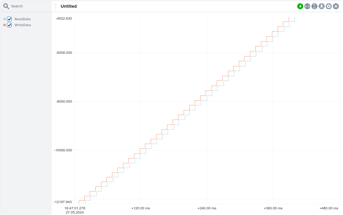
- (SHIFT) Select ReadData and WriteData and right-click to add it to Plot. See How to Analyze a System for more information.
- Select Analyze mode, and verify that ReadData follows WriteData:
For more more information about Modbus in CDP Studio, see the Modbus Configuration Manual.
Get started with CDP Studio today
Let us help you take your great ideas and turn them into the products your customer will love.