Table Editor
Table Editor
The Table Editor shows a compact representation of a system structure. Each table groups node children of one type and allows setting/monitoring their attributes.
Navigation
To view a specific Component's configuration, select it in the Project tree. Some objects such as Signals and Parameters will also have more detailed configuration available. To view this information, click the button in front of their name in the section.
The Configure mode toolbar has back and forward navigation buttons as well as a location bar which displays the path of the current selected object. You can select any parent object in the location bar to navigate to it. Selecting the current object however will list all its siblings, allowing quick switching between objects of the same type.
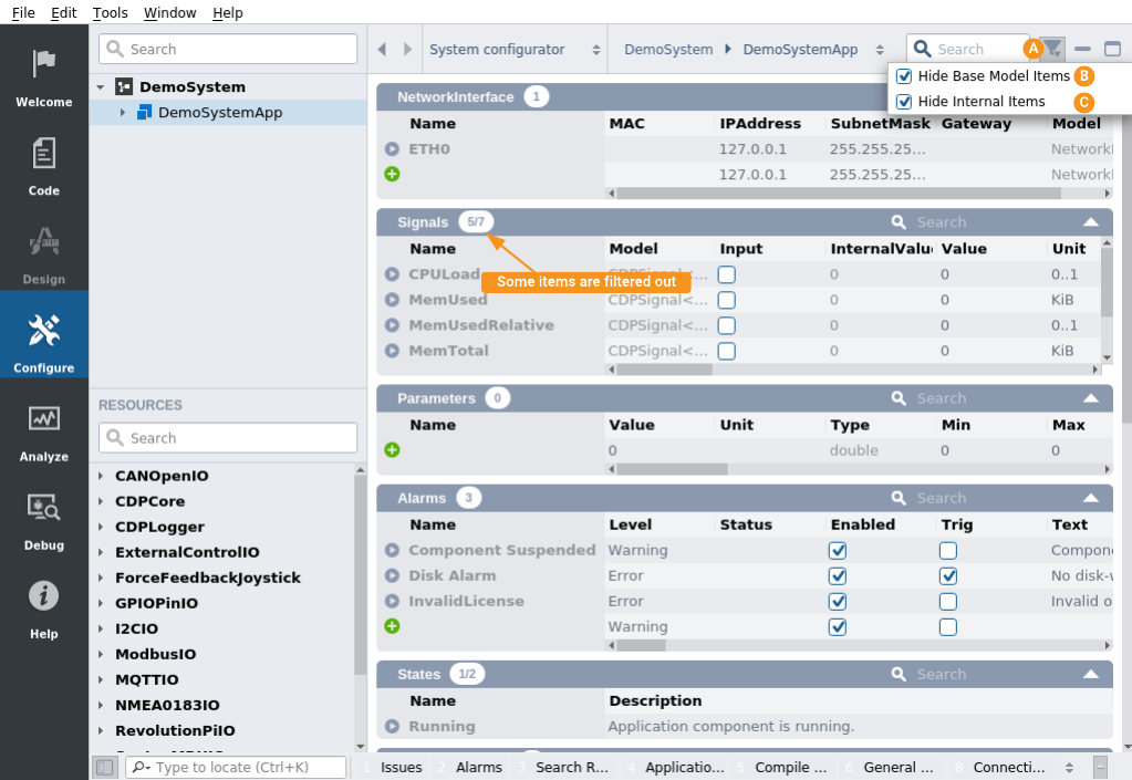
Filtering
By default, some nodes displayed in Table Editor are filtered out. To toggle filters, do the following:
- In the Configure mode toolbar click on the filter icon.
- Toggle Hide Base Model Items filter. This hides all nodes that are inherited from node's base model except nodes having Important flag (or DisplayHint="Important" in model).
- Toggle Hide Internal Items. When enabled, nodes having Internal flag (or DisplayHint="Internal" in model) are hidden from tables.
Configure Application
Editing Properties
To edit a property of an object, click on its table cell and enter a new value. Some types of properties have special editing mechanisms, such as checkboxes, combo boxes or autocompletion. Note that read-only or missing properties will be greyed out and can not be selected. For editable objects, it is also possible to change its Model; Please see How to Change the Model for more information about this.
Tip: You can use searchbox of the section to filter the content based on the input
Multi-Row (Bulk) Edit
Multiple rows of property tables can be changed simultaneously by selecting rows and applying changes to selection at once.
Rows can be selected in many ways:
- by holding down Ctrl key and clicking on name field of row
- by clicking on name field of the range start row and then, holding down Shift key, clicking on the name field of range end row
- by right clicking on name field of any row and by choosing Select All from the context menu
- by clicking on the Name column header current selection will be inverted. F.e. if no rows were previously selected then this will select all rows.
Selected rows will be shown highlighted.
When rows are selected, you can change properties in all of them just by editing the value in one row. Property values in corresponding column in all selected rows will be changed to the same value automatically.
You can rename selected rows by right clicking on the name field of any row and by choosing Rename from the context menu. All rows will be renamed based on the new base name entered (by adding numbers at the end of the new base name).
Note: Multi-row edit will not change read-only values. Also, multi-row does not accept you to enter values that will not fit into all selected rows (f.e. you can not enter negative value into signed type cell in cases when row of unsigned type is in selection).
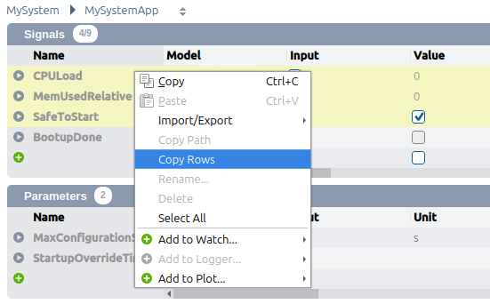
Table Copy
In addition to the standard copy/paste of configuration described in Copy/Paste and Export/Import of Configuration, there is an additional Copy Row(s) option in the context menu of the Table Editor. This option allows copying the selected rows without subelements (shallow copy) to the clipboard in a tab-separated table format, which can easily be pasted into a spreadsheet application. This can be useful when the standard CDP Studio Table Editor bulk editing features are not sufficient.
When copying rows, the following rules apply:
- You can select multiple rows using Ctrl or Shift keys.
- The first two columns saved to the clipboard are always "Name" and "Model", which are needed for pasting the data back into CDP Studio.
- For the rest, only the visible columns are copied. Click on the table header to select which columns to show.
When done editing, you can paste the data back into CDP Studio Table Editor using standard paste (Ctrl+V or context menu).
Paste Format
- The data must be in a tabular format, with columns separated by tabs and rows separated by newlines. This is the standard format when copying data from spreadsheet applications.
- The first row must contain the column headers, which must match the child node names of the object type being edited.
- The first two columns must be "Name" and "Model". These are mandatory and must be present in the pasted data.
- The order of the columns does not matter when pasting as long as the "Name" and "Model" columns are the first two.
- When pasting, it does not matter if the columns are visible or not. If the node has a child node with the same name as a column, that child node will be updated.
- Deeper nodes can be updated by using dot notation, e.g. "ChildNode.Property".
For example, a spreadsheet with the following table could be copied and pasted into a CDP application:
| Name | Model | Amplitude | Amplitude.Unit |
|---|---|---|---|
| Power supply | Sine | 230 | V |
This would create a new component named "Power supply" with model "Sine". The "Amplitude" signal in the Sine component would be set to a value of 230 and the "Unit" property of the "Amplitude" signal would be set to "V".
Conflict Resolution
When pasting rows into a table, if a row with the same name already exists, a conflict resolution dialog will appear asking how to handle the conflict. There are 4 strategies to choose from:
- Add - will add the conflicting object as a new object (by adding number at the end of the original name)
- Replace - replace the conflicting object (remove original and add new from paste/import)
- Merge - keep the conflicting object as is and paste/import content properties or subelements into it
- Skip - do not paste/import the conflicting object and its properties nor subelements
Configuring Network Interface
Several NetworkInterfaces can be defined, one for each ethernet adapter, and must have unique names. To give a specific adapter a specified IPAddress, make sure that the MAC attribute is correct, if not, the adapters are assigned in the order they are found by the CDP network-detection algorithm.
If you specify a network address that is not found in a network adapter, CDP will assign it the ip address 127.0.0.1. Subsequent non-existing ip-addresses will each be assigned a unique localhost address.
To change the network interface configuration, open the NetworkInterface property in the configuration editor. In the opened view, click the edit icon and fill in the desired configuration.
Adding Components
- In the Project tree select the application or a component, to which You will be adding subcomponents.
- In Resource tree right click a component that You want to add.
- Select "Add" in the context menu.
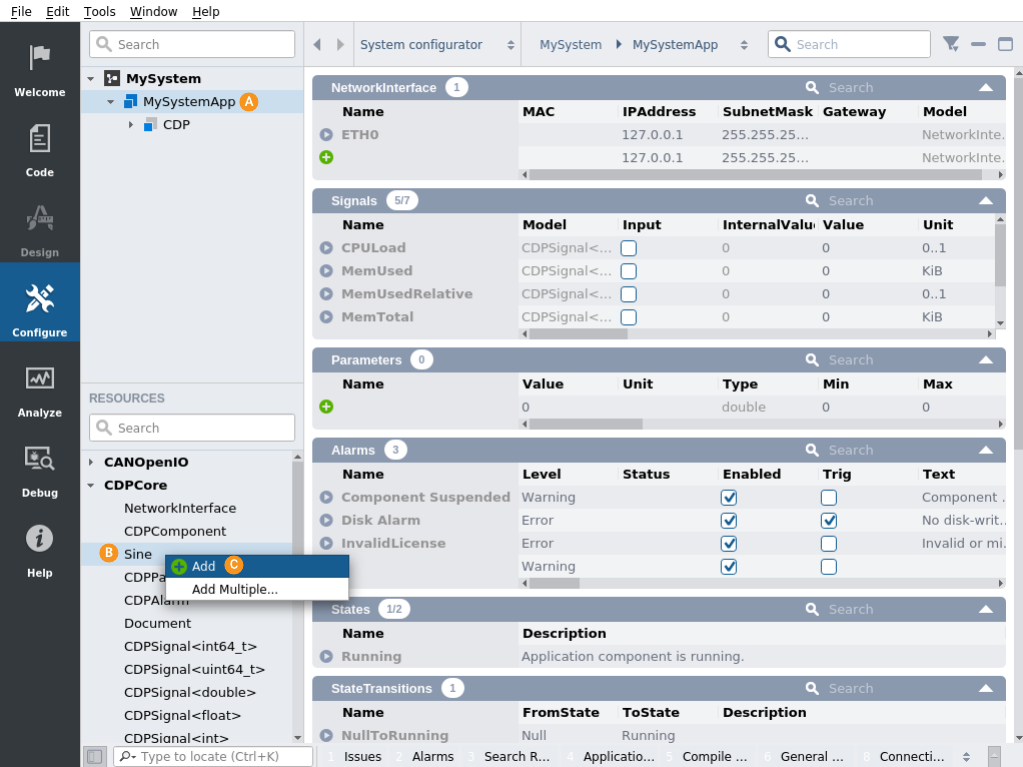
Added Components of a system are visible in the Project tree and in the Subcomponents table.
Removing Components
To remove a component from an application, right click its name in the Project tree or in the Subcomponents section and select Delete.... In Configuration editor Sections it is possible to use Shift or Ctrl keys to select multiple names for removal.
Configure Components
"Activate" Property
The "Activate" value must be set to "1" if the component is to be activated when it is created. A component must be activated to receive messages and run the periodic process. If you set activate to a number greater than 1, this is the number of seconds to pass before the component is activated. If you set activate to 0, the component will start as suspended.
Members
Subcomponents, remote connections, alarms, signals, parameters and properties are all members of the component.
The normal procedure for component configuration is simply to edit the settings for the already defined members. Components will often use relative paths in the configuration, which often means that it is not necessary to edit the component configuration when creating a new instance.
But, it is also possible to add additional members in the component.
A compressed description with a summary of what to be aware of is presented here for the different member types.
Adding Members to a Component
Component Sections which support adding additional members will display an extra row. Here you can input the configuration of the extra member. Clicking the "+" button will add it to the section.
Members can also be added from the Resource tree.
Subcomponents
Subcomponents are specified in the Subcomponents section, usually no changes necessary.
Signals
Signal routing should be verified and may have to be set up individually for each component instance. In Configure mode, the Issues pane will show all broken routings (when not connected to the system).
Alarms
Alarms have many configuration setting, pay attention to references to signals or components.
Parameters
Parameter values should be verified and changed if necessary.
I/OServers
Several additional manuals describe their setup in user manuals. See help mode to find more information about specific IOServers.
Get started with CDP Studio today
Let us help you take your great ideas and turn them into the products your customer will love.