DHChain Visualizer
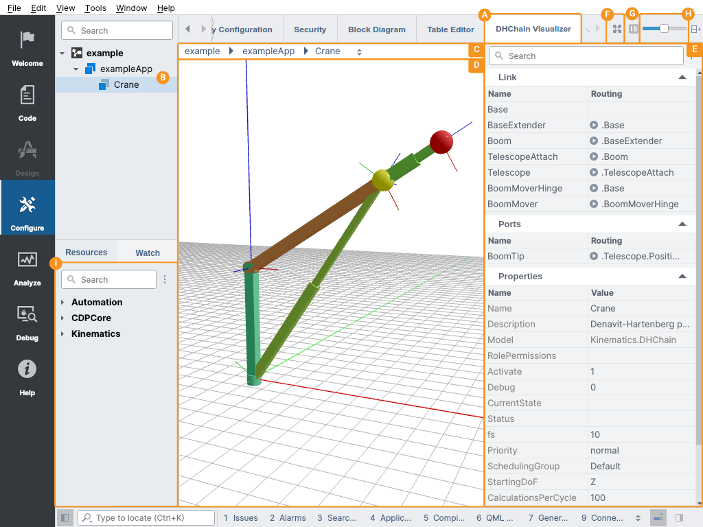
DHChain Visualizer
To help to construct and inspect Denavit–Hartenberg (DH) parameter-based kinematic chains CDP Studio has a dedicated editor for DHChain components.
The DHChain Visualizer shows up as a separate, additional Configure mode editor tab , whenever any DHChain based component is selected from the structure tree .
DHChain Visualizer shows a visual representation of the kinematic chain in the 3D space. Chain links and their position constraints can be inspected and all changes to their parameters will be visualized instantly.
DHChain Visualizer consists of:
- Location bar - displays the path of the currently selected object and can be used to directly navigate to any object in the location path.
- 3D visualization pane - shows DHChain elements visualized using 3D perspective projection. The pane has a grid drawn on the cartesian X-Y plane and the coordinate axes (red for X, green for Y, and blue for Z, towards the axes positive direction) are drawn from the cartesian zero point.
- Sidebar - displays and allows changing of properties of the selected object.
Note: Sidebar width can be adjusted by dragging the line between the 3D visualization pane and the Sidebar left or right.
Navigation in the Visualizer
The model in the 3D visualization area can be interacted with in various ways:
| Keypress or mouse move | Action |
|---|---|
| Dragging using the left mouse button | Moves the viewpoint around (without rotating it) |
| Arrow keys | |
| Dragging using the right mouse button | Moves the viewpoint around while keeping the view center in place (rotating around the chain model) |
| Alt + Arrow keys | |
| Mouse scroll wheel | Moves the viewpoint forwards and backward (zooms the chain model in and out) |
| Page up and page down keys | |
| Fit in view button | Rescales the chain based on the farthest extent of the chain links and then repositions the view to the center. |
| Shift + F key | |
| Alt key + {Fit in view} button | Rescales the chain based on the farthest extent of the chain links and then repositions the view to the center, but with the Z-axis oriented downwards. |
| Alt + Shift + F key | |
| Escape key | Moves the viewpoint so that the entire scene is fully visible (including the floor grid) |
| Adjust link width slider | Changes the width of the bars used to visualize the links and constraints. |
| Set visualization target selector (in online mode) | Can be used to select if to visualize links based on the degree of freedom parameter input or DHChain solved values, or both. When both positions are selected to be visualized, links according to the solved degree of freedom parameter values are visualized as transparent. This selector is available only in online mode. In offline mode only link positions based on the input values of the degree of freedom parameter are visualized. |
| Clicking on the link or constraint or endpoint | selects (highlights) the corresponding object and navigates the sidebar to show its properties |
| Clicking on the link or constraint name at the sidebar | |
| Ctrl + click on the link or constraint body | Multi-selects (highlights) corresponding objects |
| Ctrl-clicking on the link or constraint name at the sidebar | |
| Delete key | Prompts for deletion of the selected links or constraints |
| Clicking with the right button on the link or constraint | Shows the context menu for the object (with actions like Rename or Delete) |
| Double-clicking on the name on the sidebar | Highlights the link body in the 3D pane and navigates the sidebar into the object, to show the object properties |
Adding and Connecting Links
Links can be added from the Resource tree by drag-and-drop to the 3D visualization pane or by right-clicking on a link resource and selecting Add. A link will be added using the default (but changeable) DH parameters. Every new link added will be colored randomly (based on the link name) except for fixed-joint links that are colored using the same color as the predecessor link.
All links are visualized by drawing differently shaped bars for DH Z and X offsets (DH A and D parameters):
| Link type | Description | Example |
|---|---|---|
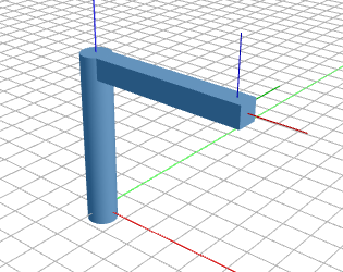
| Revolute link | Degree of freedom (rotating) offset (i.e. DH D parameter) is visualized as a cylinder, fixed offset (i.e. DH A parameter) is visualized as a cuboid |
|
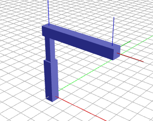
| Prismatic link | Degree of freedom (sliding) offset (i.e. DH D parameter) is visualized using two cuboids sliding into each other, fixed offset (i.e. DH A parameter) is visualized as a cuboid |
|
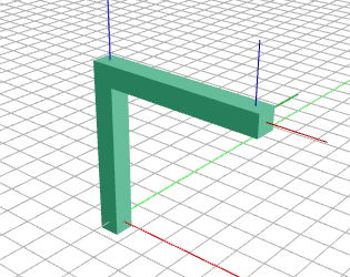
| Fixed link | Both offsets (i.e. DH A and D parameters) are visualized as cuboids |
|
After adding the link, it can be selected (as described in Navigation in the Visualizer) and its DH properties and connection (Routing) can be altered according to the need.
At the end of every link, the transformed coordinate axes are drawn as lines (red for X, green for Y, and blue for Z-axis, towards the axes positive direction), to visualize the link transformation. Transformation of the link is configurable by DH Alpha and Theta parameters of the link.
To connect a link to some other (predecessor) link end a Routing property of the link must be set to the predecessor link relative or full name (path). It can also be done without typing the name in, by using the Routing field editor helper, which will suggest a list of all existing object names after the relative routing starting mark . is entered into the field.
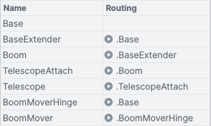
The table below shows an example of how the links can be connected by using the Routing field
Note: Any other Configure mode editor (like the Block Diagram) can also be used to connect the links or to get different visualization aspects of the link interconnections.
Adding and Connecting Positions
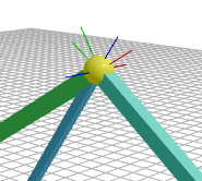
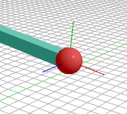
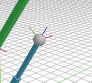
Positions can be added from the Resource tree by drag-and-drop to the 3D visualization pane or by right-clicking on a Position resource and selecting Add. Positions will be added by default to the position X=0, Y=0, Z=0, and unconnected. Positions are visualized as spheres colored based on the Position purpose:
| Purpose | Description | Color |
|---|---|---|
| Calculated Position | Output Position, routed from some link end | red |
| Constraint Position | Input Position, routed to some link PositionConstraint | red |
| Start Position | Input Position, routed to some link | green |
| Unconnected | Not routed to or from any link or PositionConstraint | gray |
After adding the position, it can be selected (as described in Navigation in the Visualizer) and its DH, connection (Routing) and direction (Input) properties can be altered according to the need.
Adding Position Constraints
For inverse kinematic calculation, an unlimited number of position constraints can be set to the links that the DHChain solver will take into account while moving the links when the application is running.
After selecting a link (see Navigation in the Visualizer), PositionConstraints can be added from the Resource tree by drag-and-drop to the 3D visualization pane or by right-clicking on a PositionConstraint resource and selecting Add. PositionConstraints will be added by default unconnected. PositionConstraints are visualized as two spheres connected by the cylinder - one sphere positioned at the link end and another positioned at the point the constraint is configured to "instruct" the link end to move to.
PositionConstraint color depends on the constraint purpose:
| Purpose | Description | Color | Example |
|---|---|---|---|
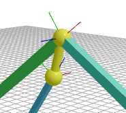
| Loop Constraint | Routed from any link Position port | yellow | Unsatisfied:
|
| Satisfied:
| |||
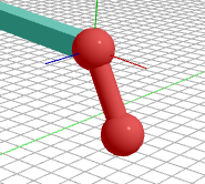
| Fixed Position Constraint | Routed from some other Position port | red | Unsatisfied:
|
| Satisfied:
| |||
| Unconnected Constraint | Not routed to any Position port | gray |
|
After adding the PositionConstrain, it can be selected and its connection (i.e. Routing property) can be altered according to the need.
Note: In offline mode, Studio does not try to satisfy the position constraints (i.e. does not perform kinematic solving). Added constraints cause the links to move (i.e. change their degree of freedom parameters) only in online mode - i.e. when the application is running.
Adding Joint Limits
After selecting a link (see Navigation in the Visualizer), Limits for the degree of freedom can be added from the Resource tree by drag-and-drop to the 3D visualization pane or by right-clicking on a Limits resource and selecting Add. Limits are not visualized in the 3D pane. They can be inspected and altered using the sidebar.
Note: In offline mode, Studio will not consider the joint limits. Joint limits will be used by DHChain solver only when the application is running.
Get started with CDP Studio today
Let us help you take your great ideas and turn them into the products your customer will love.