FMI Co-Simulation
Introduction
The CDP FMI2Cosimulation operator enables importing of simulation models compliant with the FMI 2.0 Co-Simulation standard into your CDP applications.
The Functional Mock-up Interface (FMI) is a tool-independent standard for the exchange of simulation models. It defines a standardized interface for the integration of simulation models into computer simulations, facilitating the development of complex cyber-physical systems.
This standard defines a container, known as a Functional Mock-up Unit (FMU), for exchanging dynamic simulation models. An FMU is basically a ZIP file containing XML files, binaries, and C code, facilitating portability and tool independence. It is supported by 200+ tools and maintained as a Modelica Association Project.
By using FMUs, simulation models can then be shared and reused across different platforms, enabling collaborative development and system-level simulation without requiring specific tool dependencies. FMI aims to improve interoperability, reduce integration effort, and enhance model reusability, leading to a more streamlined, scalable, and cost-effective development process for multi-domain and complex engineering systems.
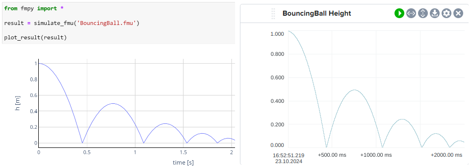
BouncingBall python example from https://fmi-standard.org/ and the same FMU in CDP Studio Analyze mode
The FMI2Cosimulation operator can load and execute FMUs (Functional Mock-up Units) that follow the FMI 2.0 Co-Simulation standard.
Quick links:
Supported Platforms
The imported FMU files include pre-compiled binaries for various platforms but according to the FMI 2.0 standard, only x86 architecture is supported. As CDP only provides 64-bit toolkits for x86, the following platforms are compatible with the FMI2Cosimulation operator:
- Windows 64-bit
- Linux 64-bit
Note: Support for ARM architectures was introduced in FMI 3.0.
Usage
To use the FMI2Cosimulation operator, it is recommended to first run the FMU Discoverer tool which scans the FMU file and automatically generates the necessary configuration.
Configuring With FMU Discoverer
Running the FMU Discoverer
- Create a system.
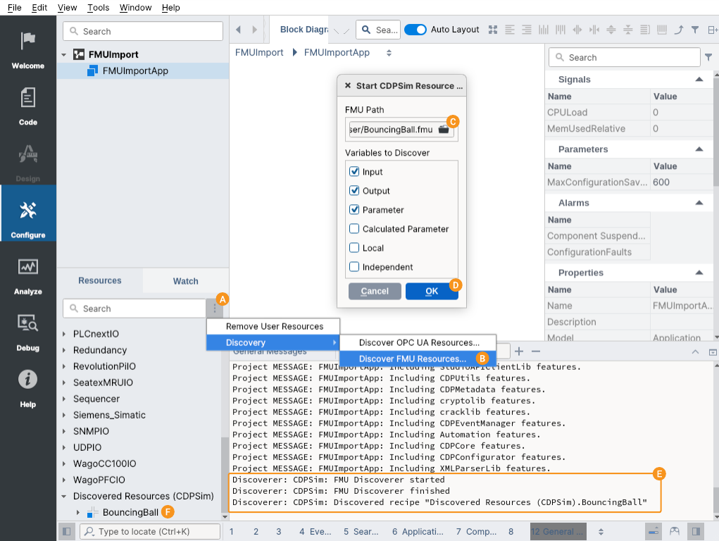
- Click on the options menu next to the resource search and select Discover FMU Resources... from the context menu.
- Click to browse the FMU. Either provide the path to a .fmu file or the already unzipped FMU directory.
- Select the types of variables to discover (hover to see the tooltips for more information). Usually, the default options are sufficient but the others can be useful for debugging.
- Press OK to start the discovery.
- Optionally, have a look at the General Messages pane for the discoverer output. Any errors will be displayed there.
- If successful, the discovered configuration will be available in the Resource tree.
Adding the Discovered FMU to the System
- From the Resource tree, add the discovered FMU .
- Optionally, adjust the FMUPath property which after discovery will be the absolute path to the FMU on your local PC.
- For smaller FMUs or remote deployments, it is recommended to click the browse button when editing the FMUPath and use the CDP Studio file dialog to select the FMU file and enable the "Copy the file to application folder" option. This ensures the FMU is copied to the project and automatically deployed with the system to the target device.
- For larger FMUs (which can be several GB) or local deployments, it is advisable to manually unzip the FMU and provide the path to the unzipped directory. This approach helps avoid long deployment times, multiple copies consuming disk space, and slow startup times (as the application would otherwise need to unzip the FMU at startup).
- Optionally, for readability, rename any of the discovered variables and remove any unnecessary ones. Keep only variables which are needed for syncing data between the FMU and the CDP application or are useful for monitoring the FMU's internal state.
- Optionally, adjust the AutoStart and Debug properties as needed.
- If AutoStart is
false, send the Start message to begin the simulation.
Tips
- In a regular CDP application, the FMI2Cosimulation operator is executed with the parent component's fs (frequency). If necessary add the operator into a dummy container CDPComponent to set the desired frequency.
Note: For FMUs with heavy computational loads, it is advisable to set the SchedulingGroup property of the parent component to something other than
"Default"(each scheduling group runs in its own thread). See Priority levels and scheduling groups for more information. - If the FMI2Cosimulation operator is added to a Simulator Application within a DynamicSimComponent then the simulation time step along with simulation start, stop and reset will be managed by the SimulatorManager component.
Note: The AutoStart property is ignored when using SimulatorManager, as the simulation start is managed by the manager.
- Disable the OverrideFMUStartValue property of an FMIVariable to prevent the Value property from overriding the FMU's default start value.
- During runtime, stop the simulation (with the Stop message) to edit output variables and fixed parameters. During simulation, only inputs and tunable parameters can be modified.
- The Debug property can be used to set the debug level of the FMU, allowing for more detailed logging if needed.
Manual Configuration
While the FMU Discoverer tool can automatically generate the configuration for an FMU, one can also manually configure the FMU by following these steps:
- From the Resource tree, add a CDPSim.FMI2Cosimulation operator to your component.
- Configure the operator with the path to your FMU file via the FMUPath property. Either provide the path to the FMU file or the already unzipped FMU directory.
- From the Resource tree, add one or more FMIVariables into the FMI2Cosimulation operator to define the variables to be exchanged between the FMU and the CDP application.
- Set up the variables by specifying FMUMapping (the full, unique name of the variable in the FMU) and check the Input property if the variable is an input.
Note: If the FMUMapping property of an FMIVariable is empty, the variable Name will be used to map to the FMU variable. However, using the FMUMapping property is recommended to avoid conflicts with reserved characters in CDP names (e.g., dots and slashes are not allowed).
- Either set the Value (the initial value) or uncheck OverrideFMUStartValue (whether the Value overrides the FMU's default start value).
The rest of the configuration is the same as for the discovered FMU.
Configuration
Properties
The following properties are available for configuration:
| Name | Type | Description |
|---|---|---|
| FMUPath | string | Path to the FMU file or the unzipped FMU directory. Note that only FMUs following the FMI 2.0 Co-Simulation standard are supported. |
| AutoStart | bool | If true, the simulation starts automatically when the application runs. If false, you need to send the Start message to begin the simulation.Note: The property is ignored if the application contains a SimulatorManager. |
| Debug | int | Debug level. Increase to get more detailed debug output from the FMU.
|
| FMUState | string (read-only) | The current state of the FMU in the simulation ("Uninstantiated", "Instantiated" or "Step mode"). |
| FMUStatus | string (read-only) | The last status reported by the FMU ("OK", "Warning", "Discard", "Error", "Fatal" or "Pending"). |
Messages
The following messages can be sent to control the simulation:
| Name | Description |
|---|---|
| Start | Starts the simulation. Use when AutoStart is false or when the simulation has been stopped. |
| Stop | Stops the simulation. |
| Reset | Resets the FMU, restoring all variables (except parameters) to their default values. |
FMIVariable
Each FMIVariable element represents a variable to be exchanged with the FMU.
Properties
| Name | Type | Description |
|---|---|---|
| FMUMapping | string | The full, unique name of the variable in the FMU. If empty, the node name is used instead. |
| Value | T | The initial value of the variable unless OverrideFMUStartValue is false. During runtime, displays the current value of the variable.Tip! Stop the simulation to edit output variables and fixed parameters. During simulation, only inputs and tunable parameters can be modified. |
| OverrideFMUStartValue | bool | If true, the Value property overrides the FMU's start value. If false, the FMU's default start value is used. |
| Input | bool | Specifies if the variable appears on the input or output side of Block Diagram. It does not affect the FMU. |
| Unit | string | The unit of the variable. |
| Routing | string | Specifies the CDP routing of the variable, e.g. where to read the inputs. |
In addition to the above properties, the FMIVariable element shows the following read-only settings. These are retrieved from the FMU for information purposes and cannot be modified:
| Name | Type | Description |
|---|---|---|
| Causality | string (read-only) | The causality of the variable as defined in the FMU (e.g., "input", "output", "parameter"). |
| Variability | string (read-only) | The variability of the variable as defined in the FMU (e.g., "continuous", "discrete", "constant"). |
| Quantity | string (read-only) | The physical quantity associated with the variable. |
| Min | T (read-only) | The minimum value of the variable. |
| Max | T (read-only) | The maximum value of the variable. |
| Nominal | T (read-only) | The nominal value of the variable. |
Error Handling
If the FMI2Cosimulation operator fails to load an FMU or encounters an error during simulation, it reports configuration faults:
- The FMUState property may show
"Uninstantiated". - The FMUStatus property may indicate
"Error"or"Fatal". - The ConfigurationFaults alarm of the parent component is set. Check the CDP Studio Alarms pane for more information about the error.
- All errors are printed to the CDP Studio Application Output pane. Set the Debug property to
2to also get info and verbose level printouts.
Example - Bouncing Ball FMU
This example demonstrates how to configure an FMI2Cosimulation operator to run the standard reference "Bouncing Ball" FMU. The FMU simulates a ball bouncing on the ground, with the height and velocity of the ball as output variables.
You can download the FMI 2.0 reference FMU files, including the BouncingBall, from the Modelica GitHub page.
Setup
- Add a container CDPComponent to your system.
- Configure the container component fs as needed. This will determine the simulation time step.
- Add an FMI2Cosimulation operator named
"BouncingBall"to your component. - Set the AutoStart property to
falseto manually control the simulation start. - Set the FMUPath property to the location of your FMU file, e.g.,
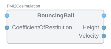
"BouncingBall-v2.0.fmu". - Add some FMIVariables to the operator:
- Height: An output variable representing the height of the ball.
- Set Input to
false. - Set FMUMapping to
"h". - Set Value to the initial height, e.g.,
100.
- Set Input to
- Velocity: An output variable representing the velocity of the ball.
- Set Input to
false. - Set FMUMapping to
"v".
- Set Input to
- CoefficientOfRestitution: A parameter controlling the bounciness of the ball.
- Set Input to
true. - Set FMUMapping to
"e". - Set Value to
0.9.
- Set Input to
- Height: An output variable representing the height of the ball.
Running the Simulation and Verifying Results
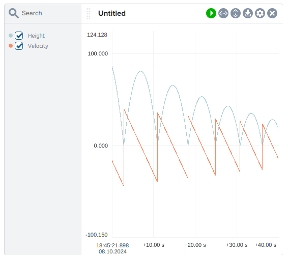
- Right-click on the Height and Velocity variables and select Add to Plot.
- Run the system.
- Start the simulation by sending the Start message to the operator.
- Observe the outputs (Height and Velocity) as the simulation progresses.
- Check Analyze mode to view the Height and Velocity variables in the plot.
Simulation Control
- During simulation, you can modify tunable parameters (e.g., CoefficientOfRestitution) even while the simulation is running.
- Outputs are read-only during simulation but become read-write when the simulation is stopped.
- During the simulation, outputs (Height and Velocity) are updated according to the FMU's logic.
- To stop the simulation, send the Stop message.
- To reset the FMU, send the Reset message. This restores all variables (except parameters) to their initial values.
Handling Variable Limits
The FMU may define minimum and maximum values for variables:
- Attempting to set a value below the minimum will result in the variable being set to the minimum.
- Attempting to set a value above the maximum will result in the variable being set to the maximum.
- For example, CoefficientOfRestitution has a minimum of
0.5and a maximum of1:- Setting it to
0.4will result in it being set to0.5. - Setting it to
1.1will result in it being set to1.
- Setting it to
See Also
Get started with CDP Studio today
Let us help you take your great ideas and turn them into the products your customer will love.