Intro 1: Tutorial of Connecting Variables to HMI GUI
Intro 1: Tutorial of Connecting Variables to HMI GUI
This tutorial will give you the first introduction of how to make and run a system with CDP Studio.
We will guide you through how to create a system that contains the CDP Sine component (object), a user interface (GUI) and connect these together. Then we will build, deploy and run the system on your PC.
When running the system, you will see the Sine wave value (i.e. a changing number from -1 to 1), and be able to change the Sine max amplitude:
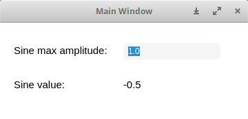
This is the step-by-step guide to create the example Intro 1: Connect Variables to HMI GUI
By completing the tutorial, you will have been through the first steps of how to create a system with CDP Studio.
Project Overview
The project consists of a simple GUI that contains 4 widgets (GUI elements) and the Sine component, a pre-made Sine generator. The example allows you to change the Sine maximum amplitude and display the current Sine value using CDP routing to connect the GUI widgets to the Sine parameters and signals.
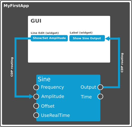
Creating the System and Application
First step in making a CDP project is to create a system and an application.
A system (project) contains one or more applications that work together to form a working control system. An application contains a collection of component instances (objects) running on a computer.
- From the 'File' menu, select 'Create New...' or click on the "New Project" button on the Welcome mode
- In the Wizard that pops up, select 'CDP System', then click on 'Choose...'
- Name the system 'MyFirstProjectTutorial', then click on 'Next >'
Note: The system name is different from the Intro 1 example to avoid problems due to a name conflict with the pre-made example
- Select version the most recent version, then click on 'Next >'
- Now we add an application by selecting Application Type GUI and naming the application MyFirstApp (instead of the default name)
- Click on 'Finish'
The system 'MyFirstProjectTutorial' containing the GUI-application 'MyFirstApp' is now created. In Configure mode, choose the 'Table Editor' tab.
Adding the Pre-made Sine Generator
CDP Studio comes with many pre-made resources. Components such as a Sine is an example of this. A component is an object, and objects can be added to an application.
- In Configure mode select MyFirstApp from the Project tree. The Resource tree is now populated with ready-made objects to choose from
- In the Resource tree, expand CDPCore by clicking in front of it
- Locate Sine in the Resource tree and double-click it to add it to the selected MyFirstApp
The pre-configured Sine generator is now added to the application and the amplitude is set to its default value 1.
Creating the Graphical User Interface (GUI)
GUIs are made in the CDP Studio Design mode. CDP Studio comes with a large set of pre-made widgets. The widgets are grouped according to category, e.g. widgets that are used for user input are grouped together under Input Widgets.
Widgets are added to the GUI by dragging them into the Form Editor, and they can be placed and resized freely. The Form Editor lets you compose widgets in a what-you-see-is-what-you-get (WYSIWYG) editor, meaning that the GUI that you get when running the application is very similar to what you see in the editor.
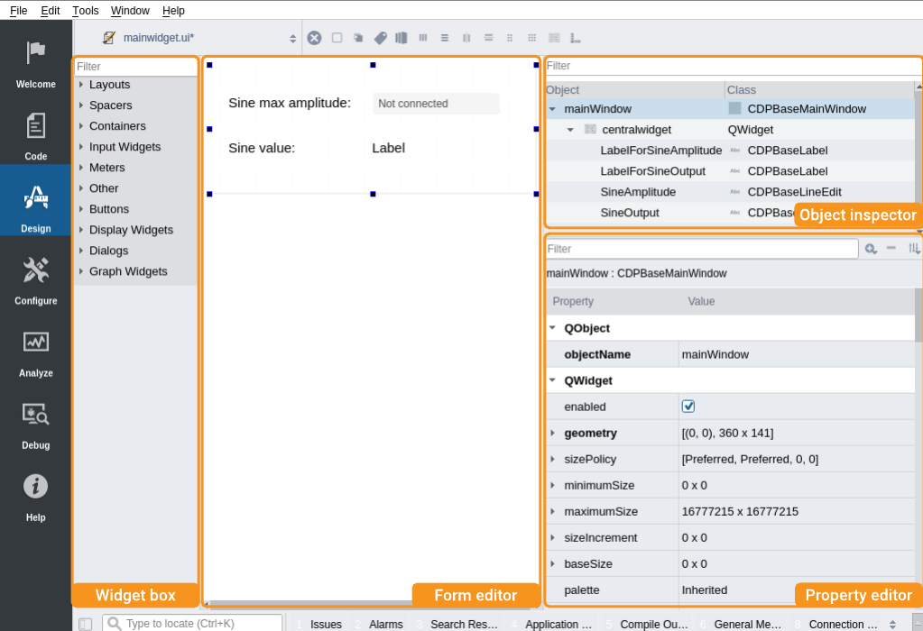
To the left there is a resource-list of graphical items (widgets) to choose from. In the center is the canvas (form) to put the widgets on. To the right is a tree-view of the gui objects at the top, and below that is a list of properties for the selected object. For more help on Design mode see the Design mode manual.
Follow the steps below to create the GUI:
- Go to Configure mode and select MyFirstApp in the Project tree. The Design mode is now selectable.
- Click on Design mode to go into the GUI editor.
- In the resource-list to the left, find the widget named Line Edit under 'Input Widgets' and drag it into the form. A Line Edit can be used to get text or numbers from a user and show text and values.
Note: You can drag the edges of the widget to resize it.
Note: To get more information about widgets or properties, hit the F1 key while the widget or property is selected. This will open Help on the relevant item. To leave help, click on the Design mode to get back to the Design view.
- Select the Line Edit in the form by clicking on it. The Properties window to the right is now populated with settings belonging to the Line Edit widget.
- Find the Property named objectName and change it to SineAmplitude
Note: Renaming widgets makes them easy to find later. Look for the widget-name in the object tree above the property window.
- Find the widget named Label under 'Display Widgets' and drag it into the form. A Label can show text and numbers.
- Rename the Label widget to SineOutput
- Drag another Label into the form and place it in front of the Line Edit widget 'SineAmplitude'. Rename it to 'LabelForSineAmplitude'. Then find the Property named text (or double-click in the Label) and enter 'Sine max amplitude:'.
- Drag another Label into the form and place it in front of the Label widget 'SineOutput'. Rename it to 'LabelForSineOutput'. Then find the Property named text (or double-click in the Label) and enter 'Sine value:'.
Connecting the GUI and the Sine Component
To be able to set and display values in SineAmplitude and SineOutput, the GUI widgets must be connected to the Sine component. The way CDP Studio connects components together, or connects GUI widgets to components, is called routing. This is an important concept in CDP Studio.
The routing to and from the GUI is set up in the GUI itself using the cdpRouting property for each widget. CDP Studio uses name-based routing uniquely defined by the syntax:
<Application>.<component>.<possibly-more-objects-inbetween>.<property>
- To connect the Output signal from the Sine component to the Label widget called SineOutput, click on the widget named SineOutput, then find the Property named cdpRouting (you may also click into the Filter in top of the property-section, and start entering 'cdpRouting'). Click in the field next to it to set the routing.
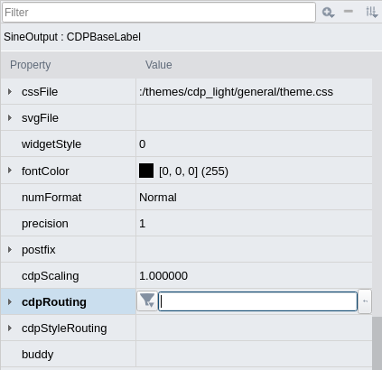
- With the cursor set in the cdpRouting field, start typing 'myfirstapp'. The Routing-selector shows available selections to choose from, and you can continue typing or select the item to route from by using arrow-keys and enter. Select the item that says MyFirstApp, then type '.' without the quotes.
- The routing-selector now shows the next available choices. We want to get data from the Sine component, so select Sine.
- Type '.' to see which items are available in Sine. We want to show the Output, so select Output.
- Hit the Enter key on your keyboard once to select and one more time to set the final routing.
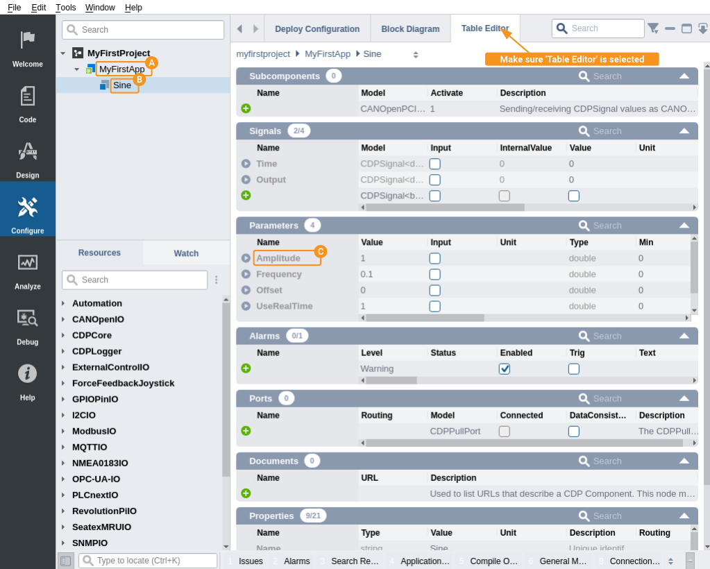
- The cdpRouting property now shows MyFirstApp.Sine.Output.Value.
Note: The Output signal you selected in the previous step has several properties that can be retrieved. Value is the default property, and that is automatically appended by the routing-selector.
- Now click on SineAmplitude in the form editor. Locate the Property named cdpRouting and click in its Value-column.
- We want to connect to MyFirstApp.Sine.Amplitude, so type that into the cdpRouting Value-column and press theEnter key to set it. The cdpRouting should now show MyFirstApp.Sine.Amplitude.Value:

- Save the form by hitting the Ctrl key + S.
Note: All names in CDP Studio are case sensitive!
Below, the tree-structure of the application is shown in the upper left view. It also shows how the routing can be composed by the names indicated by , and , to form the cdpRouting shown above.
How to Run the Tutorial
To run the tutorial from CDP Studio, select Configure mode, right-click on the system project and select Run & Connect. See the Running and Connecting to the System tutorial for more information.
Test the System
- The GUI starts up, and the Label-widget (SineOutput) shows a value changing between 1 and -1.
- Click in the LineEdit-widget (SineAmplitude), and type 100 followed by pressing the Enter key.
- In the confirm-dialog that pops up, click OK.
- The Sine in the control-system will now vary between -100 and 100.
- To stop the system, go to Configure mode in CDP Studio, right-click the System, and select Stop.
Note: If no value is showing in the GUI, or the GUI app does not show up, try re-doing the example, paying attention to each step as you go along.
Congratulations!
You have now created a GUI to show and manipulate values in a control system! You can now proceed to the next getting started example.
Inspect Real-time Info and Plot Values
A very useful feature is the possibility to see, in real time, all values in the table format and to plot values changes in a graph. This is very useful when testing, analyzing, tuning and searching for possible issues in a system.
After selecting Run & Connect, you will be connected to the running system. Select a component in Configure mode and you will see that the values change in real-time.
Visualizing the values in a graphical plot is done in Analyze mode as is described in the Analyze Mode Manual.
Get started with CDP Studio today
Let us help you take your great ideas and turn them into the products your customer will love.