Intro 4: Using Messages and States
Intro 4: Using Messages and States
This example is using a traffic light to demonstrate how a state machine is used in a component, how messages can be used to communicate between components and some more advanced GUI features in CDP Studio, the independent automation software for open PC-based real-time distributed control systems. CDP Studio provides many feature not covered by PLC IEC 61131-3 languages.
This example explains
- How to use state machines and state transitions
- How to make a re-usable component and use multiple instances in a system
- How to use messages, from GUI and from inside a component (in code)
- GUI, use of layouts and lamp widget and button to send messages
- Some tips and recommendations
Recommended: See first Intro 3: Make Reusable Objects in C++. The project files are found in the Examples section in Welcome mode.
This example is the fourth in the series Intro to CDP Studio.
Project Overview
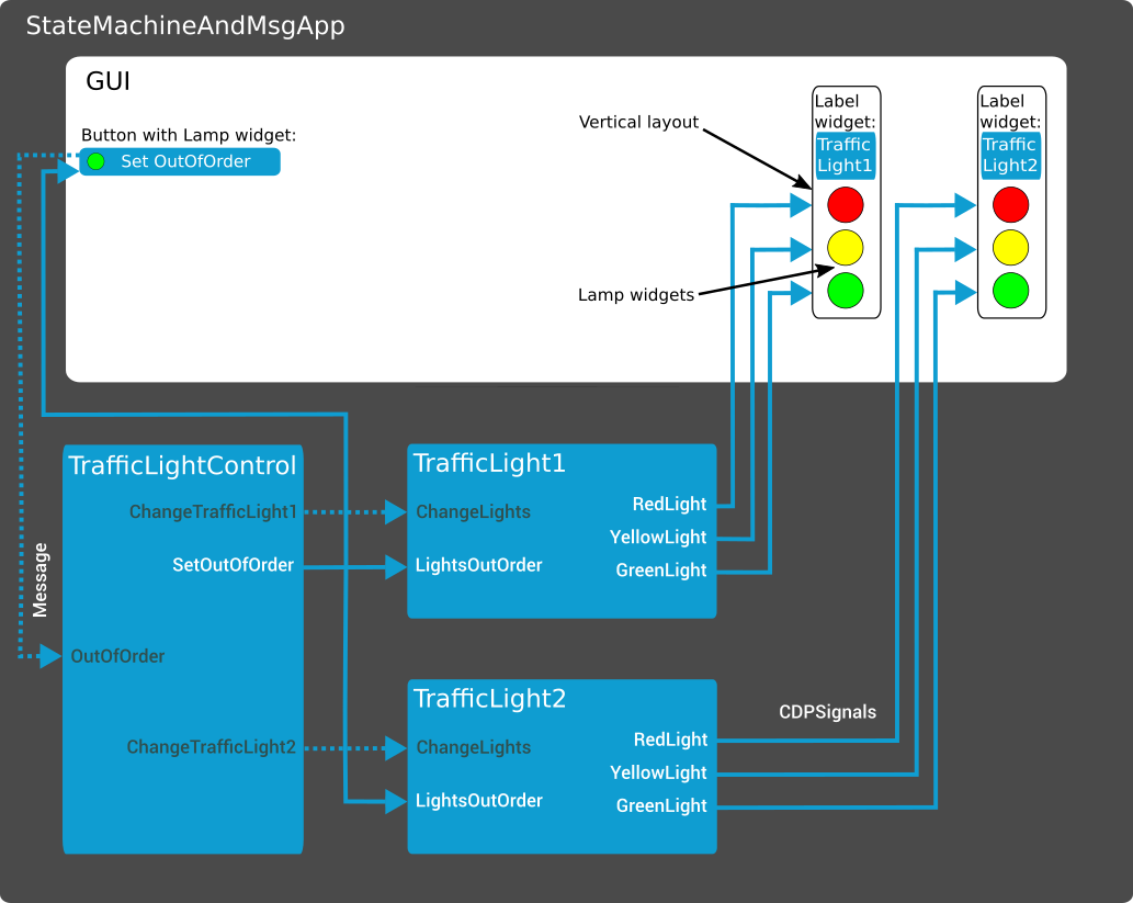
This project is traffic lights at a road junction. The library has 2 components, the overall control function for the junction and the individual traffic light. The system uses 2 instances of the traffic light and communication between the components uses messages and signals. The internal logic in the traffic light is made using a state machine. The GUI demonstrates use of layouts, sending messages to components and how to use the lamp widget.

How to Run the Example
To run the example from CDP Studio, open Welcome mode and find it under Examples. Next, in Configure mode right-click on the library project and select Build, then right-click on the system project and select Run & Connect. See the Running the Example Project tutorial for more information.
Project Description
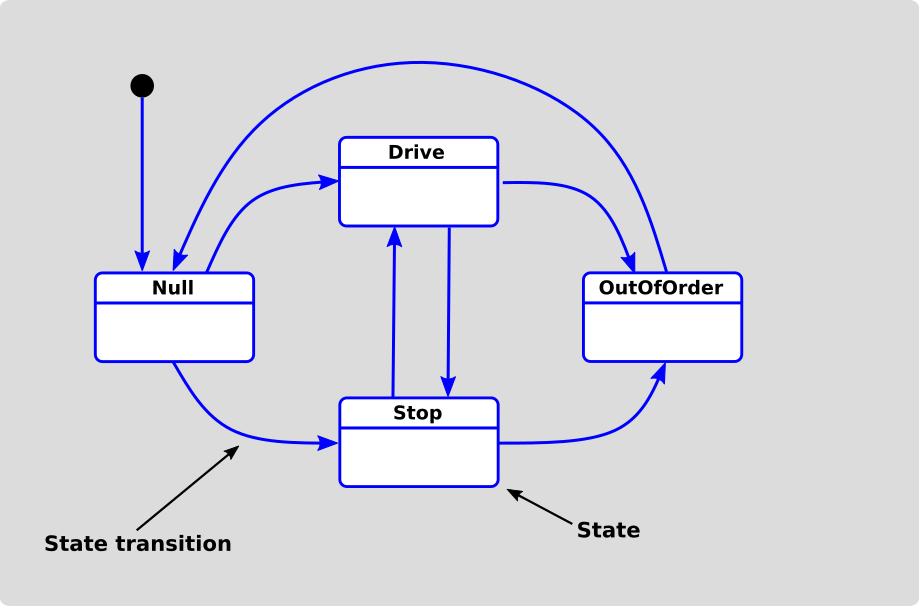
The TrafficLightControl controls the overall operation of the traffic lights. The component controls the light change interval and set the lights in out of service (this is controlled from the GUI). The initial start-up is with one traffic light in green and the other in red, defined by a CDPParameter, TrafficLightn.StartState, set in Configure mode. The TraficLight1 and TrafficLight2 are 2 instances of the re-usable component TrafficLight. The internal logic is made using a state machine. The state machine created is as seen below. A state machine always starts in state Null.

TrafficLightControl sends Messages to the TrafficLighs when these shall change, the TrafficLighs manage the change process themselves. E.g. going from the state Drive (green light) to state Stop (red light), the lamps will show yellow for some time before showing red.
The logic of changing lights is in the state transitions functions DriveToStop and StopToDrive. For the out of service blinking of lights, the logic is in the OutOfService state.
TrafficLightControl does not use a state machine and the logic is therefore all in the ProcessNull function.
Clicking the OutOfService button in the GUI will send both TrafficLighs to the state OutOfService where they will show a blinking yellow light.
The lights in the GUI traffic light visualization use the Lamp widget. The lamp colors are actually a range of different images with different colors. The cdpStyleRouting select which image to display (0 = grey, 1 = green, 2 = yellow, 4 = red).
Messages and CDPSignals are both used for communication between components and between GUI and components, this to show you both options. Messages are recommended when it is only required to trigger an event, e.g. like change the lights. Text Command Messages hold a text string of the pre-defined message.
Important Concepts to Understand: State Machine and State Transitions, Messages and New GUI Elements
This focuses on new concepts and will not describe the basic signals and properties that has been explained in the previous getting started examples or can be seen in the above system diagram. We strongly recommend reading the following sections as understanding this will save time and frustration when making your own systems.
State Machine and State Transitions
CDP Studio has built in support for state machines and state transitions. These are added to your component in Code mode by right clicking and the select “CDP->Add->…” and then using the wizards. CDP Studio autogenerates one C++ function and all required initializations per state and per state transition.
It’s important to understand how CDP executes (runs) the states and state transitions as this affects how you code the logic. CDP executes the state machine in the following way:
- Executes all state transition functions that are possible from the current state, or until one of them returns true (and then updates current state). The state transitions are executed in the order they appear in the component code.
- Executes the code that is in the current state function (
Proces<current state>).
For this example: If the TrafficLight is in state Drive, then the code is executed as follows for every cycle:
TransitionDriveToStop()TransitionDriveToOutOfOrder()ProcessDrive()
Both TransitionDriveToStop() and TransitionDriveToOutOfOrder() will return false (because requestedState is still "Drive"). When TrafficLight receives the message to change the lights (sets ChangeTheLights to true), this is detected in ProcessDrive() which sets the condition to change to the Stop state (requestedState = "Stop"). Next time TransitionDriveToStop() function is called, it will pass the first if statement (will not return false immediately), then changes the light to yellow, starts a countdown that is used as a timer, and then return false. The TransitionDriveToOutOfOrder() will continue to return false since requestedState is not "OutOfOrder". The cycle continues until the counter reaches 0 where the lights are set to red and the TransitionDriveToStop returns true. Then the current state changes to Stop.
Logic and code can be placed both in the state and state transition functions. You need to take care that code and logic in the state function and in the state transition functions are written in a way to avoid any conflicts.
Recommendation: A good rule is to only place logic in the state functions or in the state transition functions.
The state machines run as real time processes and there must not be any blocking code or lengthy logic in the functions. E.g. if you want to wait 5 seconds, then you could implement this as a counter that is updated for every run cycle. A while() loop should not be used.
Tip: Countdown timers are used in this example, and they are made to be independent of the frequency the component runs at. If ChangeLightTimer is initialized to 5, false will be returned each time until 5 seconds have elapsed:
if(ChangeLightTimer > 0){
    ChangeLightTimer = ChangeLightTimer - 1.0/GetFrequency();
    return false;
}
Tip: A timer can also be used instead, e.g. CDPTimerMs.
Messages and How to Use Messages from GUI and in Code
Messages are very useful when you want to communicate between components that do not require regular updates as a CDPSignal or hold a value. This uses far less resources than a CDP signal that will update the value at the frequency of the component.
To send and receive messages between components, you must:
- Define a message, a text string – e.g. “ChangeLights”
- Create a Connector in the sending component
- Use the SendMessage function to send the message
- Create a Messagehandler in the receiving component
The CDPConnector and Message are created in same manner as for a state or a signal. The connector name is only used within the component. You need to have 1 connector for each component you wish to send messages to. In this example we have 2 as we are sending messages from TrafficLightControl to both TrafficLight1 and TrafficLight2. The syntax to send a message is:
connectorName.SendMessage("TextCommand");
When creating the Message in the receiving component, the messagehandler function is automatically generated. The message name must be the message-name that is sent, e.g. “ChangeLights”. When the message is received, the message handler function is executed.
Tip: We recommend that the routing of the messages, i.e. the component that shall receive the message is done in the Configuration and not directly in code. This to build re-usable components. This example follows this principle, see the list of Connectors in TrafficLightApp.TrafficLightControl using Configure mode.
Sending a message from GUI widgets is easier, here the Connector is already set up by the system. Set the cdpRouting property to the component that shall receive the message and enter the message in the cdpTextCommand property.
GUI Layouts and Button with Lamp Widget
Layouts are very useful when you want to group widgets and align these horizontally or vertically. E.g. just drag a Vertical Layout to the Form editor and then drag in the widgets that you wish to group and align. You may adjust the size of the layout box by simple drag.
Tip: One traffic light was completed first with layout and all properties set. To create the second, the first traffic light was selected (same way as selecting object in Powerpoint) and then do Copy/Paste to create the second traffic light. Just remember to update the properties that is dependent on the instance, e.g. cdpStyleRouting for the lamp widgets.
The example uses the Button with Lamp widget to set the traffic lights in and out of service. To have the light on the button change to green when the button is clicked, you need to check the property “checkable”, add the routing in “cdpCheckedRouting” and uncheck “checkableByClick”. In this case we used the TrafficLightControl.SetOutOfOrder signal as it is true when the lights are out of order.
Note: The cdpCheckedRouting is bi-directional, i.e. 1) it can set a value in the control system or 2) use the control system to control if the lamp should be on or off. The property “checkableByClick” defines the direction. If checked, the button writes true/1 in the signal, if unchecked the GUI reads the value and turns lamp on or off.
Get started with CDP Studio today
Let us help you take your great ideas and turn them into the products your customer will love.