Wago PFC Setup Guide
Introduction
This guide demonstrates usage of a WagoPFCIOServer in CDP Studio, the independent automation software for open PC-based real-time distributed control systems to communicate with the following modules:
| Module Name | Description |
|---|---|
| 750-431 | 8-channel digital input |
| 750-530 | 8-channel digital output |
| 750-454 | 2-channel analog input |
| 750-554 | 2-channel analog output |
Configuring the Example
Configure Physical Wago PFC 200
Set up the Wago PFC 200 by adding the following modules to it in this order:
| Module Name | Description |
|---|---|
| 750-820x | Wago PFC 200 Controller |
| 750-431 | 8-channel digital input |
| 750-530 | 8-channel digital output |
| 750-554 | 2-channel analog output |
| 750-454 | 2-channel analog input |
| 750-600 | end-module / bus-terminator |
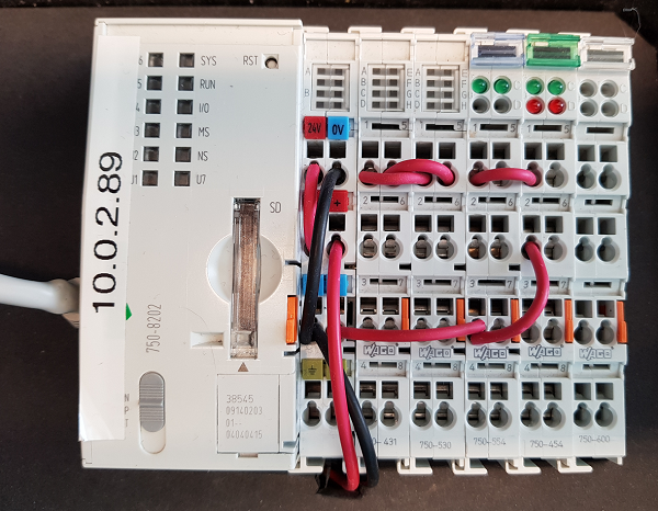
Make sure you set up power connections on the Wago PFC 200 correctly. Please refer to the Wago manuals for this. Make sure that you power the power-jumper contacts in addition to the supply contacts.
- Connect power-jumper contact 0V to 750-554.3
- Connect power-jumper contact 0V to 750-454.2
- Connect a wire from 750-454.1 to 750-554.1 so that the analog value is looped back
- Connect a wire from 750-530.1 to 750-431.1 so that the digital value is looped back
The final configuration should look something like this:
Install SD-card image
Make sure you install the Wago PFC SD-card image and set it up as detailed here.
Set up a Test-system
First we set up a System that the component can be tested in:
Create a system named WagoDemo with a Console application named WagoDemoApp, then select Configure mode. See How to Create a system for more information.
Configure the I/O Server
- Select the WagoDemoApp that resides under WagoDemo in the Project tree.
- In the Resource tree, expand WagoPFCIO and double-click the WagoPFCIOServer to add it:
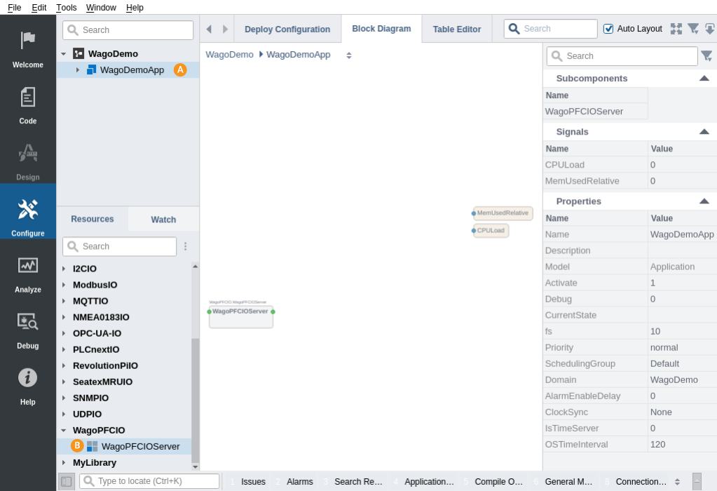
- Select the added WagoPFCIOServer in the Project tree
- The fs property must be at least 20 Hz (the default), or all the physical outputs will be set to 0 by the hardware.
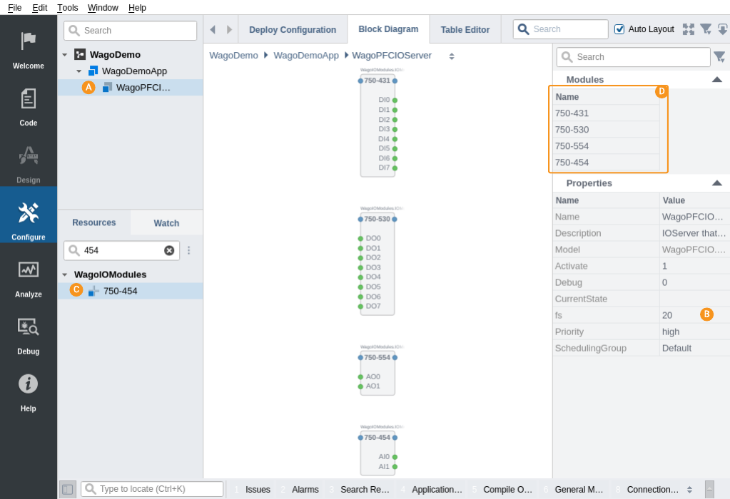
- Use the Resource tree Search Filter to search for and add the modules below (For instance, type 431 to find the first module)
- Add a 750-431 element by right-clicking Resources WagoIOModules 750-431, and then click Add
- Add a 750-530 element by right-clicking Resources WagoIOModules 750-530, and then click Add
- Add a 750-554 element by right-clicking Resources WagoIOModules 750-554, and then click Add
- Add a 750-454 element by right-clicking Resources WagoIOModules 750-454, and then click Add
The final module configuration should now look like this :
Connect the I/O to the Control System
To set a signal out to the I/O, you can connect the output of a Sine generator to a physical output:
- Select the WagoDemoApp in the Project tree.
- From the Resource tree, click into the CDPCore resource and double-click on Sine to add it to the WagoDemoApp
- Click into the newly added Sine component. Since the analog output module accepts values between 0 and 32767, we want to make the Sine generate values in that range.
- Set the parameter Value of Amplitude to 16384.
- Set the parameter Value of Offset to 16384
- Click into WagoDemoApp WagoPFCIOServer 750-554
- Set Routing in AO0 to be WagoDemoApp.Sine.Output. The routing can be set by clicking into the Routing column of AO0, and start typing Wa then press arrow down and the Enter-key, then type .Si arrow down and Enter, and .Ou arrow down and Enter. As you can see, the Routing selector pops up suggestions for the routing as you type. Hit Enter one last time to set the Routing.
Pairing and Setting Up
- Select WagoDemo in the Project tree.
- In the Networks table, select the network that the WagoPFC device is on.
- In the Devices table, find the IP-address of the Wago PFC.
- Double-click on the IP-address to rename it to WagoPFC, then type in the Username, and select 'Pair'. Enter the password if a dialog pops up.
- Right-click the device and run the Toolkit Detector to determine the best toolkit for the device.
- In the Applications table, select Device 'WagoPFC' and select the best toolkit suggested by the Toolkit Detector
Note: If the recommended toolkit is not in the toolkit list, install the missing toolkit as described here.
How to Run the Tutorial
To run the tutorial from CDP Studio, select Configure mode, right-click on the system project and select Run & Connect. See the Running and Connecting to the System tutorial for more information.
Verifying That It Works
- Click on Analyze mode.
- Add the AO0 and DO0 signals in WagoPFCIOServer to the graph, in addition to the AI0 and DI0 input signals.
- Autoscale / zoom the graph to view the signals.
- Now monitor the AO0 and AI0 in analyze mode. Here you can see the propagation delay, and you can also see the time spent converting values to/from the physical layer by monitoring the Send-Receive Roundtrip time signal in the WagoPFCIOServer component.
How to Add Unsupported / New Modules
It may be that a Wago module is not supported by CDP Studio. It can be added by configuring the module manually. Example of how to add an 8 channel Digital Output module:
- Add an IOModule element from the WagoIOModules resource
- Give the module a unique name, f.i. DigitalOutputs
- Add 8 CDPSignalChannel<bool> channels named DO0 through DO7.
- Make sure to set 'Nr' on all digital channels, as this is the 0-based bit-number that the channel is mapped to.
- Set Input to 1 for all digital channels, as they need to read values from CDP to write to the module.
- Optionally, for simple re-use, copy the module configuration and paste it into one of your libraries.
Note: Make sure that all digital channels have 'Nr' set. This is the 0-based bit-number that the channel is mapped to; Having several channels mapped to the same bit will cause problems.
Example of how to add a 2 channel Analog Input module:
- Add an IOModule element from the WagoIOModules resource
- Give the module a unique name, AnalogInputs
- Add 2 CDPSignalChannel<short> channels named AI0 and AI1.
- Check that Input is set to 0 for all channels.
You can mix and match inputs and outputs as required by the module. To find information about a module, press Ctrl+K, then type "r Wago 750-<modulenumber> manual" and select your favourite search-engine from the dropdown (replace <modulenumber> with the actual module number you are searching for), then press 'Enter'. This will open up a web browser with some search results. Download and open the PDF from http://www.wago.com, then search for 'process image' in the pdf. In that section should be a description of how the data is organized inside the module, and that info can be used to create a module as shown above.
Note: Make sure that the module configuration order matches the physical module order (All power-inserters and other non-process-data modules can either be skipped, or it is possible to insert a placeholder by adding an empty WagoIOModules.IOModule at the wanted position).
If the configuration does not match, the IOServer will print errors and go to Offline state.
Troubleshooting
If 'Run & Connect' fails with a message in the Compile Output pane mentioning 'rsync', verify that
- it is possible to connect to the device (try going into the web-interface on the Wago PFC to verify the IP address).
- you have a recent Wago PFC image. If the Compile Output pane says something like 'rsync is not found', try updating the image as mentioned in Install SD-card image.
Get started with CDP Studio today
Let us help you take your great ideas and turn them into the products your customer will love.