Connecting Components Using SimPorts
SimPort
The SimPort is a CDPPort that can aggregate multiple SimSignals to transfer a bulk of values between simulator components with a single two-way routing connection. It can be used similarly to PowerBond / Bondgraphs / Two-port systems. The SimPort can only be added to simulator components and unlike regular CDPPorts, it allows for faster data propagation with the SimulatorManager time step.
The SimPort can be used in two ways:
- As a code port meant to be used in C++ code by a DynamicSimComponent.
- As a configuration-only port meant to help structure the project and to make use of CDPOperators creating some simple no-code logic.
This manual will focus on the configuration-only use case. The code port use case is described in the class documentation.
Properties
The following properties are available for the SimPort:
| Property | Description |
|---|---|
| Input | Set true if the port is an input (routed). In Block Diagram, this will make the port appear on the left side of a block. |
| Routing | Path of a CDPNode this port communicates with - usually another SimPort. |
| Connected | True if the port is communicating with a remote object and every SimSignal having the Mandatory property checked is connected. |
| DataConsistency | Used only when connecting ports between different CDP applications. When enabled, values connected by this port are sent within the same data packet, meaning that a group of remote values always appears consistent. Otherwise when multiple values change, they may appear for a remote application in wrong order or one change might be delayed a little. This option can only be enabled when the port only connects values with periodic routing (not event-based). |
PortSimSignal
A PortSimSignal is a SimSignal added to a SimPort. For that purpose it includes a few additional properties compared to a regular SimSignal that allow customizing the connection options.
The following properties are available for the PortSimSignal:
| Property | Description |
|---|---|
| Input | Sets the data flow direction. If false, data is sent from the source component to the target component. If true, data is sent from the target component to the source component. |
| RemoteName | A value within the remote object this signal will be connected by the parent SimPort. If empty, it will automatically be set equal to the SimSignal Name - this allows easy connect when the name is same on both local and remote side. |
| Connect | Connectivity flags (D - Downstream or U - Upstream) - normally not needed unless partially taking values from port chain for processing and re-adding them later. Downstream flag can be cleared to prevent the connection from being queried from routed port API-s. Upstream flag can be cleared to hide the connection from this port API. |
| Mandatory | Indicates if this connection is mandatory to be connected for the Port to report overall successful Connected status. |
SimPort Usage
Consider a simulation with two independent components - a tractor and a wagon. The tractor can generate a pulling force. However, the resulting position and velocity will depend on the total mass of the wagon and tractor. The wagon here can be modeled as a separate component with its own state variables and properties. When multiple signals need to be shared between the components, it is better to use a SimPort rather than connecting each signal individually. This will reduce the number of connections and make the project easier to follow.
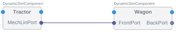
The MechLinPort (mechanics port for linear motion) itself would look like this:
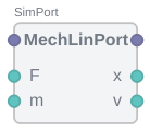
- F - Transferred force
- m - Connected mass
- v - Transferred linear velocity
- x - Transferred linear position
Here the force F and the mass m signals are sent towards the wagon and the feedback of the velocity v and the position x is returned to the tractor. All this requires making just one connection. In addition, if one wishes to improve this model, it is easy to add more signals to the port without needing to make new connections to propagate the extra signals.
The benefits of using a SimPort become even more apparent when considering a larger number of independent components that can be mixed and matched in different configurations. For example, if we have multiple wagons attached in series, we can easily add one to the diagram and connect it:
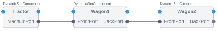
The implementation for the independent wagon here would check if there is a connection to another wagon. If there is, it would add its mass and pass the force to the next wagon. If there is no connection, it would just add its mass and calculate the acceleration based on the force from the tractor.
Now if the connection between the tractor and the wagons is not stiff, but has some flexibility, we could easily add a spring-damper component to the connection:
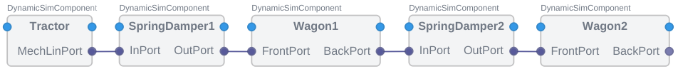
The spring-damper component would receive the force from the tractor and use it to calculate the force on the wagon while also returning the resulting velocity and position back to the tractor. However note, in this case, it might be easier to model the system if the spring would return the reaction force back to the tractor, and the tractor would calculate the resulting velocity and position. Having each component manage its own state variables and properties is a good practice to keep the project modular and easy to follow.
Configuring a SimPort
To configure a SimPort, add it to a DynamicSimComponent in Configure mode.
- From the Resource tree, add a CDPSim.SimPort to a DynamicSimComponent.
- Rename the added SimPort to match the purpose of the port, e.g. MechLinPort.
- From the Resource tree, add one or more CDPSim.PortSimSignals to the SimPort.
- Rename the PortSimSignals to match the signals to be sent through the port, e.g. F (force), m (mass), v (velocity), x (position).
- Set or clear the Input property for each signal to determine the data flow direction.
Depending on the Input property set to the PortSimSignal, data will be sent from the source component to the target component or vice versa.
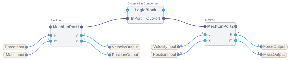
Here is a data propagation example (using just some constants routed to the port signals for simplicity). The F and m signals are sent from the left-side port to the right-side port, while v and x are sent as feedback from the right-side port to the left-side port. The MechLinPort1 and MechLinPort2 could be connected directly or passed through other components. In this example, data is passed through LogicBlock.
Ports are useful for structuring the project. To simply pass around port data without any logic, you can use a Proxy Port - an empty port with no signals. This will just pass the data from one component to another without any processing.
Note: Ports that do contain signals are called Data Ports.
If the LogicBlock from the last image would be empty and just pass data, it would look like this:
![]()
On the other hand, if you want to add data processing logic to the LogicBlock, you are allowed to "take out" the necessary signals from the SimPort, process them and then "put them back" to the port chain. For this:
- From the Resource tree, add a CDPSim.PortSimSignal to the InPort from the previous image and rename the signal to match the signal to be taken out.
- For the signal taken out, toggle the Input property, to move it to the right side of the block. Then set the Connect property to D - Downstream to remove the signal from the port chain.
- Add a CDPOperator to the LogicBlock and connect the signal taken out to the operator. Add any necessary processing logic to the operator.
- Add a PortSimSignal to the OutPort and rename the signal to match the signal to be put back.
- Toggle the Input property for the signal to be put back, to move it to the left side of the block. Then set the Connect property to U - Upstream to put the signal back to the port chain.
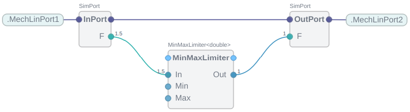
In the following image, the LogicBlock inspects the F signal and using the MinMaxLimiter operator limits the force to a certain range. The F signal is then put back to the port chain. Any signal not listed on the port block (m, v and x in this example), will be passed through without any processing.
Data Ports and Proxy Ports
As mentioned earlier, a port that contains signals is called a Data Port. A port that does not contain any signals is called a Proxy Port.
A Data Port should be used when you need to process or monitor the signals contained in the port. However, be cautious when using Data Ports, as they can introduce a delay in the data propagation chain. Each step processes all components and their child ports in the order they appear, passing data from one port signal to the next. Therefore, ensure the order of components and ports is optimal for the simulation. The order of components and ports can be changed by reordering them in the Configure mode Subcomponents and Ports tables as described in the Basics: Architecture manual. Additionally, for ports that pass data in both directions, there is no good way to ensure data is passed in one cycle, so one direction may be propagated faster than the other.
When possible, prefer using a Proxy Port. It eliminates the problem of data propagation delay since it does not contain any intermediate signals that need to sync data and display their values. Instead, the signals at the start and end of the port chain are directly connected.
Get started with CDP Studio today
Let us help you take your great ideas and turn them into the products your customer will love.