Using Modbus RTU on Adam-4150
Using Modbus RTU on Adam-4150
The purpose of this example is to show how to use and setup a Modbus RTU device in CDP Studio, the independent automation software for open PC-based real-time distributed control systems with simple NoCode programming similar to PLC IEC 61131-3 function block diagram.
This example uses an Adam-4150 Modbus RTU device and has a GUI for visualization and control.
This example includes
- A simple system (project) and application
- A Modbus RTU master (to communicate with an Adam-4150 device)
- A GUI to visualize the I/Os and the state of the modbus communication
- Routings between the GUI widgets and the Modbus master
Prerequisites:
- An Adam-4150 Modbus RTU device, set up with baudrate 19200,8,N,1
- A shunt or short wire that connects DO0 with DI0 on the Adam-4150
- A USB to RS/485 converter
Project Overview
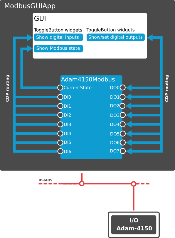
The project consists of a GUI that contains several Lamp and Toggle Button widgets (GUI elements) and the ModbusMasterRTU component. The example allows you to change the digital outputs of the Adam-4150 from the GUI, and to observe the digital inputs coming from the Adam-4150.
Before you run the project, make sure to set the correct ComPort in the SerialTransport inside ModbusGUIApp.Adam4150Modbus. The ComPort is the port that the RS/485 converter the Adam-4150 physical device is connected to.
How to Run the Example
To run the example from CDP Studio, open Welcome mode and find it under Examples. Next, in Configure mode right-click on the system project and select Run & Connect. See the Running the Example Project tutorial for more information.
Project Description
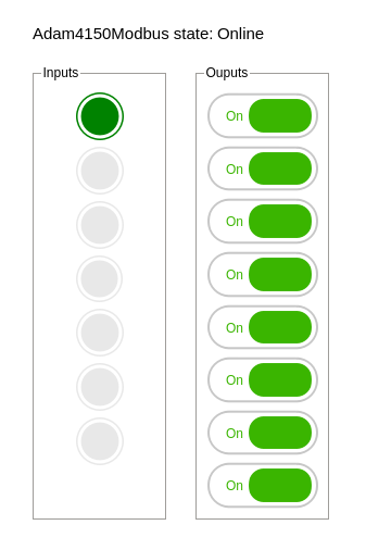
The application has 7 Lamp widgets inside the Inputs groupbox, and 8 Toggle Buttons inside the Outputs groupbox. At the top there is a label to show the state of the ModbusMasterRTU I/O (The label is named ModbusState). All the inputs can not be toggled (the enabled property in the widget is set to 0), but the outputs can be toggled on or off.
The Adam4150Modbus component is a ModbusMasterRTU component that is configured to communicate with the Adam-4150 physical slave device. The Adam-4150 exposes 7 digital inputs from Modbus read address 0 and 8 digital outputs from Modbus write address 16. To access the data, the Adam4150Modbus component has two packets set up:

The Read packet has FunctionCode ReadDiscreteInputs to read the input bits, while the Write packet has FunctionCode WriteMultipleCoils to write the output bits. To get more information about setting up Modbus, see the Modbus Configuration Manual.
GUI Configuration
The GUI configuration can be seen in Design mode:
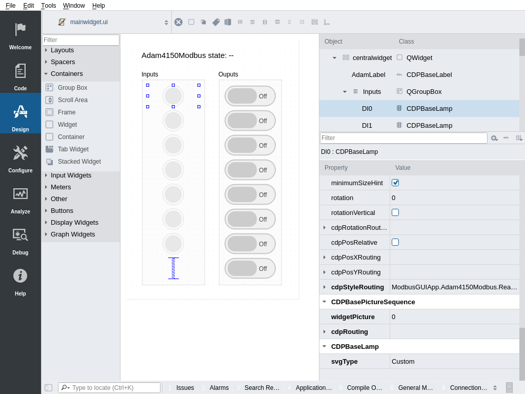
- Input Lamp DI0 has cdpRouting set to ModbusGUIApp.Adam4150Modbus.Read.Digital.DI0
- Input Lamp DI1 has cdpRouting set to ModbusGUIApp.Adam4150Modbus.Read.Digital.DI1, and so on. The Adam-4150 has 7 inputs, DI0 - DI6.
- Output Toggle Button DO0 has cdpRouting set to ModbusGUIApp.Adam4150Modbus.Write.Digital.DO0
- Output Toggle Button DO1 has cdpRouting set to ModbusGUIApp.Adam4150Modbus.Write.Digital.DO1 and so on.
When the application is running and all is set up correctly, toggle all outputs to on. The Adam-4150 module now looks something like this:
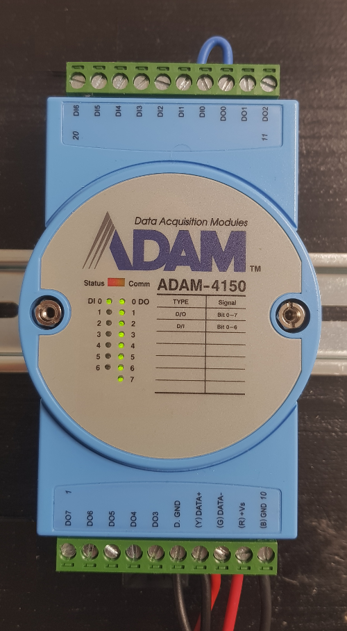
If you toggle DO0, you will also see that DI0 toggles. This is due to the shunt that connects DO0 and DI0.
Troubleshooting
If there are communication-issues, please verify all the items in the list below:
- Check that the Adam module has power and that the status light is blinking.
- Check that the Adam module mode switch is set to 'Normal'
- Check that the wiring between the Adam module and the rs/485 converter is correct
- Check that the rs/485 converter is connected to the target computer
- Check that the ComPort in the SerialTransport inside ModbusGUIApp.Adam4150Modbus is set to the ComPort that the rs/485 converter is at. (on Windows, the ComPort is typically '\\.\COM3' or similar, while on Linux the comport might be '/dev/ttyUSB0'
- Check that the Adam module is set up according to the BaudRate, Parity, DataBits and StopBits in SerialTransport:

Note: The Property Debug in ModbusGUIApp.Adam4150Modbus can be set to the value 2. This will cause the Adam4150Modbus to write out each telegram it sends along with connection information
Get started with CDP Studio today
Let us help you take your great ideas and turn them into the products your customer will love.