Making an Automation System with HMI GUI
The purpose of this example is to show a practical project that make use of many functions and general concepts that are important when developing solutions with CDP Studio, the independent automation software for open PC-based real-time distributed control systems.
Included are step-by-step guide, code examples to develop the application and a description on how to create a more advanced GUI.
This example demonstrates:
- A practical approach and steps required to create a solution
- How to create libraries and reusable components with state machines and logic
- How to use multiple instances of a component in a project
- How to build a system with routing signals between component instances
- How to create a comprehensive GUI with layouts, spacers and different widgets
- How to connect the GUI widgets and control system components
Creating this example from scratch using the step-by-step guides is a good way of learning how to develop solutions with CDP Studio.
How to Run the Example
To run the example from CDP Studio, open Welcome mode and find it under Examples. Next, in Configure mode right-click on the library project and select Build, then right-click on the system project and select Run & Connect. See the Running the Example Project tutorial for more information.
Project overview
The project is a fish feeding system where you can feed fish from 2 food tanks. The feeding system allows you to specify feeding rates, amounts, delayed start independently for the 2 tanks. The solution allows you to fill the tanks, gives a status overview and different alarms.
The tanks have individual screw pumps that moves the food from the tank into a pipe and they share a blower that blows the food through the pipes and into the fish cage.
Project Description
The typical steps to take when developing a CDP Solution are:
- Decide the structure and which components that is required and must be developed (FishTank, Blower, GuiInterface)
- Create a library and develop these components using C++
- Create the system, add the required components (2 FishTank, 1 Blower, 1 GuiInterface)
- Connect the components together to make a working system in Configure mode using the Block Diagram (drag-and-drop graphic view) or System Configurator (table view)
- Design and create the GUI, connect the widgets to the components
Tip Use the Model Editor to create the signals, parameters etc to simplify the C++ coding instead of using the wizards from the Code mode. The Model Editor will autogenerate the required C++ code.
The following chapters show how to create the project from scratch.
Create New Library
First we need to create a new library project. See: How to Create a Library. Name it "TankControlLib". We have now created an empty library, but it has nothing useful in it quite yet.
Create a FishTank Component in Your Newly Created Library
In this section we will be making a new component called "FishTank".
Create the Component
First we need to create the component itself. See How to add a component model to see how it is done. When the component is created it will open in Code Mode. If in the future you need to open the component source files manually, you can do it by navigating to it from the Project tree while being in the Code mode:
- Expand "TankControlLib"
- Expand "Sources"
- Double-click on the file "FishTank.cpp"
Add CDP Members to the Component
We will now populate our component. Here we add signals, parameters, states (CDP Studio is a state machine based tool) and the state transitions we will need. We will first disregard the code, but add all states, signals, parameters we want. We'll come back to the code later when all components are placed.
Go through following sections and add CDP members to the FishTank component.
See also: How to add CDP members to class
Signals
Add following Signals to the FishTank component.
It is smart to tick the "Create Another" checkbox, then it will automatically pop up a new signal generation wizard after clicking "Ok".
| Name | Type | Input | Value |
|---|---|---|---|
| PauseButton | bool | x | |
| FeedingInProgress | bool | ||
| FillScrewActive | bool | ||
| ScrewActive | bool | ||
| MaxLevelAlarm | bool | ||
| AlarmLow | bool | ||
| AlarmExtremeLow | bool | ||
| AlarmStatus | int | ||
| BlowerActive | bool | x | |
| TankLevel | double | 100 | |
| ScrewSpeed | double | 1 | |
| FillAmount | double | 50 | |
| FeedAmount | double | 50 | |
| RemainingTime | double | ||
| StartTime | double | ||
| TimeFeeded | double |
If you checked the "Create another" checkbox earlier then in order to end creating signals, simply press "Cancel".
Parameters
Here we enter some values that determine when the alarms should be activated. The parameters represent physical sensors, that would be in the tank but since we are simulating this, we use them to compare with the tank level and base the alarm states from that. Add parameters in this table:
| Name | Unit | Value |
|---|---|---|
| AlarmLevelLow | litre (l) | 30 |
| AlarmLevelExtremeLow | litre (l) | 10 |
| MaxValue | litre (l) | 100 |
| FillingSpeed | litre/s (l/s) | 2 |
States
Add following states to the FishTank component.
| Name | Description |
|---|---|
| Filling | Fill up the tank with the desired amount of food |
| Feeding | System will start feeding |
| FeedingStopped | Feeding and filling are both stopped |
| AutoStarting | Waiting to start after a given time delay |
State Transitions
We have now created Signals and States. We will now create transitions from one state to another.
- Right click on empty space in FishTank.cpp or FishTank.h
- Select "CDP" -> "Add" -> "State Transitions"
You should now see a window showing all the states you have created in both the left and the right box.
From the left box choose the state to transition from, and from the right box, the state to transition to.
CDP Studio always auto-generates and adds a state "Null". This is the first state the system enters when the application starts. Remember to tick the "Create another" for convenience.
Add your transitions according to the table:
| From | To |
|---|---|
| Null | FeedingStopped |
| FeedingStopped | Filling |
| FeedingStopped | Feeding |
| FeedingStopped | AutoStarting |
| Filling | FeedingStopped |
| Feeding | FeedingStopped |
| AutoStarting | FeedingStopped |
| AutoStarting | Feeding |
Message Handlers
Later we will want to control the FishTanks using GUI. The most logical way to activate certain processes or state transitions would be to do them based on some event that happened (for example a button was pressed). For event based control, CDP provides Messages that can be sent from one CDP object to another. As the FishTank is the object to be controlled, it is at the receiving end of messages and should therefore have a way to handle each message. Next we will be creating Message Handlers for each message, that we will later be sending from the GUI.
- Right click on empty space in FishTank.cpp or FishTank.h
- Select "CDP" -> "Add" -> "Message"
Create the following message handlers:
| Message text command | Description |
|---|---|
| StartFeeding | Switches the state to Feeding |
| StartFilling | Switches the state to Filling |
| AutoStartFeeding | Switches the state to AutoStarting |
| Stop | Switches the state to FeedingStopped |
| SpeedUp | Increases the screw speed |
| SpeedDown | Decreases the screw speed |
Now we have created everything we need to start writing the functionality for the FishTank.
Functionality
States
Let's start by implementing each state.
When we generated states for the component, CDP automatically generated a method for each state with a name similar to this...
void FishTank::ProcessMyStateName()
{
}
...where the "MyStateName" part of the method name is replaced with the name of the actual state generated.
When in a particular state, the associated method gets periodically called and the code in it executed. The frequency of the calling is defined by the component's property 'fs', which is inherited from the parent class of FishTank which for components is always CDPComponent. 'fs' can be configured in Configure mode.
The implementation of each state is initially empty, so we need to provide our own functionality here.
State “Null”
Since state "Null" actually makes no sense for an actual system (as "null" basically means "no state") we will leave the implementation of method FishTank::ProcessNull() empty.
void FishTank::ProcessNull()
{
}
State "Filling"
When the FishTank is in the state "Filling" the tank level should rise and the fill amount should drop at the speed specified by FillingSpeed parameter. Also the filling screw should be turned on. To achieve the correct filling speed, we have to divide the FillingSpeed value by 'fs' value, to make the filling independent of the processing frequency of the component.
        FillScrewActive = true;
        TankLevel = TankLevel + FillingSpeed/GetFrequency();
        FillAmount = FillAmount - FillingSpeed/GetFrequency();
Obviously we have to stop filling the tank, when it is full, or if fill amount runs to 0. At either of those cases, we will be turning off the filling screw and changing the state to "FeedingStopped". To make sure that FillAmount does not go below 0, we will explicitly set it to 0 and for the TankLevel we will implement something similar.
    if (FillAmount <= 0)
    {
        FillAmount = 0;
        FillScrewActive = false;
        requestedState = "FeedingStopped";
    }
    else if (TankLevel >= MaxValue)
    {
        TankLevel = MaxValue;
        FillScrewActive = false;
        requestedState = "FeedingStopped";
    }
Finally we have to make sure that the alarms are updated, so we will call a method named FishTank::processAlarms() which we will look into later.
In conclusion the method will look like this:
void FishTank::ProcessFilling()
{
    if (FillAmount <= 0)
    {
        FillAmount = 0;
        FillScrewActive = false;
        requestedState = "FeedingStopped";
    }
    else if (TankLevel >= MaxValue)
    {
        TankLevel = MaxValue;
        FillScrewActive = false;
        requestedState = "FeedingStopped";
    }
    else
    {
        FillScrewActive = true;
        TankLevel = TankLevel + FillingSpeed/GetFrequency();
        FillAmount = FillAmount - FillingSpeed/GetFrequency();
        processAlarms();
    }
}
State "Feeding"
When the FishTank is in the state "Feeding", then the TankLevel should lower at the rate, specified by ScrewSpeed.
- When in "Feeding" state, set FeedingInProgress to true
- If TankLevel or FeedAmount reaches 0, then end feeding
- When first entering the Feeding state, then start counting total feeding time
- If Pause is active, then stop FeedingScrew
- Reduce TankLevel and FeedAmount and also calculate remaining time estimation
- When exiting "Feeding" state, then set FeedingInProgress and ScrewActive to false
- Alarms need to be processed.
- m_feedingInitialized should be declared in header file and initialized to false in constructor
Taking all the requirements into account, the code looks like this:
void FishTank::ProcessFeeding()
{
    if (TankLevel <= 0)
    {
        TankLevel = 0;
        FeedingInProgress = false;
        ScrewActive = false;
        m_feedingInitialized = false;
        requestedState = "FeedingStopped";
        return;
    }
    else if (FeedAmount <= 0)
    {
        FeedAmount = 0;
        FeedingInProgress = false;
        ScrewActive = false;
        m_feedingInitialized = false;
        requestedState = "FeedingStopped";
        return;
    }

    if (!m_feedingInitialized)
    {
        TimeFeeded = 0;
        m_feedingInitialized = true;
    }

    FeedingInProgress = true;
    TimeFeeded = TimeFeeded + 1.0/GetFrequency();
    if (PauseButton)
    {
        ScrewActive = false;
        return;
    }

    ScrewActive = true;
    RemainingTime = (FeedAmount/ScrewSpeed);

    TankLevel = TankLevel - ScrewSpeed/GetFrequency();
    if (TankLevel<0)
        TankLevel = 0;
    FeedAmount = FeedAmount - ScrewSpeed/GetFrequency();
    if (FeedAmount<0)
        FeedAmount = 0;
    processAlarms();
}
State "FeedingStopped"
When in state "FeedingStopped" there are no active processes. All we need to do, is calculate the remaining time estimation for when the user changes the ScrewSpeed. Also we need to process alarms.
void FishTank::ProcessFeedingStopped()
{
    FillScrewActive = false;
    ScrewActive = false;
    FeedingInProgress = false;
    RemainingTime = (FeedAmount/ScrewSpeed);
    processAlarms();
}
State "AutoStarting"
In the state "AutoStarting" we need to count down from the StartTime, set by the user and enter the "Feeding" state when the countdown reaches 0.
void FishTank::ProcessAutoStarting()
{
    if (StartTime > 0)
        StartTime = StartTime - 1.0/GetFrequency();
    else
    {
        StartTime = 0;
        requestedState = "Feeding";
    }
}
State Transitions
When a component is in a certain state, then all state transition methods, that are from that state, are called. It is the state transition method's job to return true, if the automatically created variable "requestedState" has the correct value. The default implementations for state transitions are therefore suitable for our application with one exception. We want the state to change from "Null" to "FeedingStopped" as soon as possible regardless of whether the requestedState has been set to "FeedingStopped" or not. The easiest way to achieve this is to return true from FishTank::TransitionNullToFeedingStopped().
bool FishTank::TransitionNullToFeedingStopped()
{
    return true;
}
Processing Alarms
Every time the tank level changes, we need to check if we need to activate an alarm. For that we will create a method for this called "processAlarms". As you saw earlier, we already have added the calls for the method so now we only need to provide an implementation.
void FishTank::processAlarms()
{
    MaxLevelAlarm = TankLevel >= (MaxValue * 0.999);
    AlarmLow = TankLevel <= AlarmLevelLow;
    AlarmExtremeLow = TankLevel <= AlarmLevelExtremeLow;

    AlarmStatus = 0;
    if(MaxLevelAlarm)
        AlarmStatus = 3;
    else if(AlarmExtremeLow)
        AlarmStatus = 1;
    else if(AlarmLow)
        AlarmStatus = 2;
}
Don't forget to add the declaration of the method in the header file.
Message Handlers
All we have left in the FishTank component are the message handlers. 4 of the message handlers that we created are used for changing the state of the component. Therefore we only need to set a new value for the "requestedState".
int FishTank::MessageAutoStartFeeding(void* /*message*/)
{
    requestedState="AutoStarting";
    return 1;
}

int FishTank::MessageStartFeeding(void* /*message*/)
{
    requestedState="Feeding";
    return 1;
}

int FishTank::MessageStop(void* /*message*/)
{
    requestedState="FeedingStopped";
    return 1;
}

int FishTank::MessageStartFilling(void* /*message*/)
{
    requestedState="Filling";
    return 1;
}
The other 2 message handlers we are going to use for increasing and decreasing the ScrewSpeed variable:
int FishTank::MessageSpeedUp(void* /*message*/)
{
    if (ScrewSpeed < 5)
        ScrewSpeed = ScrewSpeed + 0.5;
    return 1;
}

int FishTank::MessageSpeedDown(void* /*message*/)
{
    if (ScrewSpeed > 0.5)
        ScrewSpeed = ScrewSpeed - 0.5;
    return 1;
}
Create Blower Component in TankControlLib
In this section we will be making a new component called "Blower". The process is similar to how we created the "FishTank" component here.
Add CDP Members to the Blower Component
Signals
| Name | Type | Input |
|---|---|---|
| FeedingActiveTank1 | bool | x |
| FeedingActiveTank2 | bool | x |
| BlowerActive | bool |
Timer
To add a timer, we first need to add a parameter and then rename the type "CDPParameter" to "CDPParameterTimer". So add a regular CDPParameter called "DelayTime" and change its type to "CDPParameterTimer". You also need to change the include from <CDPParameter/CDPParameter.h> to <OSAPI/Timer/CDPParameterTimer.h>.
States
| Name | Description |
|---|---|
| Running | Blower running |
| Stop | Blower is turned off after a time delay |
State Transitions
Add the following state transitions:
| From | To |
|---|---|
| Null | Stop |
| Stop | Running |
| Running | Stop |
Functionality
States
State "Null"
Just like with the "FishTank" component, the "Null" state does not make much sense for the Blower component, so we will leave the ProcessNull method empty.
void Blower::ProcessNull()
{
}
State "Stop"
When the Blower is stopped, we will be checking if any one of the FishTanks has started working, so we can also turn on the Blower. We will be using the signals "FeedingActiveTank1" and "FeedingActiveTank2" that we added earlier for this. Also we set the "BlowerActive" signal to false. This will be showed on the GUI later on.
void Blower::ProcessStop()
{
    BlowerActive = false;
    if (FeedingActiveTank1 || FeedingActiveTank2)
        requestedState = "Running";
}
State "Running"
When the Blower is running, we set the signal "BlowerActive" to true. We also check if both of the FishTanks have been off for over 15 seconds and if they have then we will also change the Blower's state to "Stop".
void Blower::ProcessRunning()
{
    BlowerActive = true;

    if (FeedingActiveTank1 || FeedingActiveTank2)
        DelayTime.Restart();
    else if(DelayTime.TimeElapsed() > 15.0)
        requestedState = "Stop";
}
State Transitions
We will do the exact same thing with state transitions as we did for the "FishTank" component, leaving all state transitions, except for the one originating from state "Null", to their default implementations. And again we will simply return true from the transition from state "Null" to state "Stop".
bool Blower::TransitionNullToStop()
{
    return true;
}
Create GuiInterface Component in TankControlLib
In this section we will be making a new component called "GuiInterface". The process is similar to how we created the "FishTank" component here. The purpose of this component is to forward the user inputs received from the GUI to the correct components.
Add CDP Members to the GuiInterface Component
Signals
| Name | Type | Input |
|---|---|---|
| Pause | bool | x |
Connectors
- Right click on empty space in GuiInterface.cpp or GuiInterface.h
- Select "CDP" -> "Add" -> "Connectors"
The connectors will be used to forward CDPMessages from the GUI to other components. Add 2 connectors called FishTank1 and FishTank2.
Message Handlers
We will add 1 message handler to the component:
| Message text command | Description |
|---|---|
| StartFeeding | Switches the state to Feeding |
Functionality
States
Although CDP provides each component with a state-machine, we will not be using it for the GuiInterface component. That is also the reason, why we did not create any states for the component. As for the default "Null" state, we will just leave its implementation empty.
void GuiInterface::ProcessNull()
{
}
Connectors
We need to specify what the connectors should be connected to. As this can not yet be done from the Configure mode we will have to hard-code the routings in the source code of the component. We will do this in the Configure() method.
void GuiInterface::Configure(const char* componentXML)
{
    CDPComponent::Configure(componentXML);
    FishTank1.ConnectTo("FishTankControlApp.FishTank1");
    FishTank2.ConnectTo("FishTankControlApp.FishTank2");
}
Note that "FishTankControlApp.FishTank1" and "FishTankControlApp.FishTank2" refer to actual instances of the FishTank component, that we have not yet created. We will do that later in the tutorial.
Message Handler
Earlier we created a single message handler for a message "StartFeeding". CDP automatically generated a message handler method called GuiInterface::MessageStartFeeding() and a message registration command in the GuiInterface::CreateModel() method:
RegisterMessage(CM_TEXTCOMMAND,"StartFeeding","",(CDPOBJECT_MESSAGEHANDLER)&GuiInterface::MessageStartFeeding);
However, we will need to forward 3 other messages beside the "StartFeeding" message. Because the GuiInterface component does not need to differentiate between all those messages, we will be using a single message handler for all messages named GuiInterface::MessageForwardMessage(). So we need to rename the method GuiInterface::MessageStartFeeding() to GuiInterface::MessageForwardMessage().
- Right click on the method name
- Move the cursor to "Refactor"
- Choose "Rename Symbol Under Cursor"
- Name the method "ForwardMessage"
This will change the method name in both the .cpp and .h files as well as in the RegisterMessage call in the CreateModel method. Next we need to register the remaining 3 messages to use this message handler. For this we will simply copy the RegisterMessage commands 3 times and change the message name as follows:
void GuiInterface::CreateModel()
{
    CDPComponent::CreateModel();

    RegisterStateProcess("Null",(CDPCOMPONENT_STATEPROCESS)&GuiInterface::ProcessNull,"Initial Null state");
    RegisterMessage(CM_TEXTCOMMAND,"StartFeeding","",(CDPOBJECT_MESSAGEHANDLER)&GuiInterface::MessageForwardMessage);
    RegisterMessage(CM_TEXTCOMMAND,"Stop","",(CDPOBJECT_MESSAGEHANDLER)&GuiInterface::MessageForwardMessage);
    RegisterMessage(CM_TEXTCOMMAND,"StartFilling","",(CDPOBJECT_MESSAGEHANDLER)&GuiInterface::MessageForwardMessage);
    RegisterMessage(CM_TEXTCOMMAND,"AutoStartFeeding","",(CDPOBJECT_MESSAGEHANDLER)&GuiInterface::MessageForwardMessage);
}
The GuiInterface::MessageForwardMessage() method should be like this:
int GuiInterface::MessageForwardMessage(void* message)
{
    FishTank1.SendMessage(static_cast<MessageTextCommand*>(message)->textCommand);
    FishTank2.SendMessage(static_cast<MessageTextCommand*>(message)->textCommand);
    return 1;
}
Build the Library
After we have created the components, we need to build the library. Doing this will make the components available in the Configure mode. There they can be added to applications.
See also: How to build a library
You will see a status bar down to the right in the screen which shows the progress of building. This should not take long. When the building is finished, go to Configure mode.
Create New System
- In Welcome mode create a new system and call it "FishTankControl".
See also: How to Create a System
Add Components to the Application
After you created a new system called "FishTankControl" you should have an application under it called "FishTankControlApp" by default. Now we will add the previously created components to that application.
- Add two FishTanks
- Add one Blower
- Add one GuiInterface
See also: How to Add Components
Once this is done you should see the components in your application. If you click on one of them, you will see all the configuration options that are associated with this component.
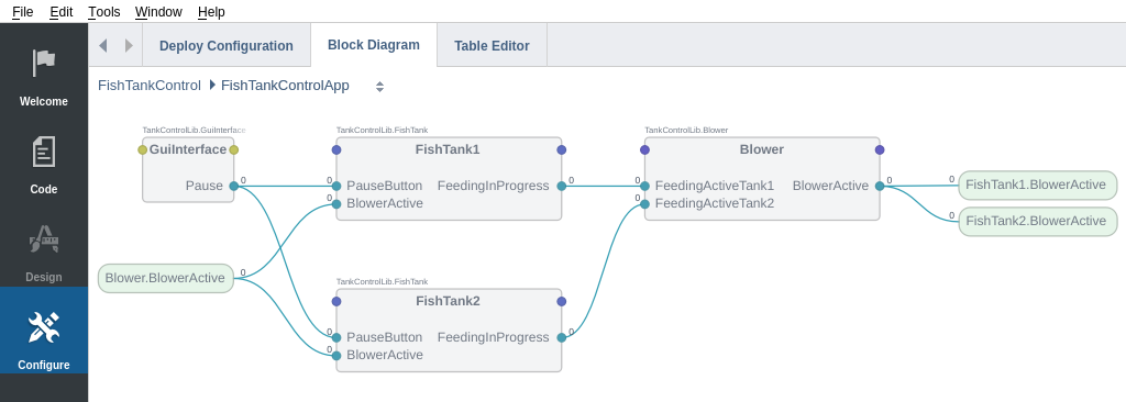
Routing the Signals
We will now set up what are called routings. Simply put, a routing is an address from where an input signal should get its value. See also: How to set up routing
FishTank Components' Configurations
Do the following for both the FishTank components we added earlier:
- Switch to Configure mode (if you are not already)
- Select one of the FishTank components from the Project tree
- Navigate to the heading "Signals" in the Configuration editor
- For the "BlowerActive" signal set the routing to: "FishTankControlApp.Blower.BlowerActive"
- For the "PauseButton" signal set the routing to: "FishTankControlApp.GuiInterface.Pause"
| Signal's name | Routing |
|---|---|
| BlowerActive | FishTankControlApp.Blower.BlowerActive |
| PauseButton | FishTankControlApp.GuiInterface.Pause |
Blower Component's Configuration
Do the following for the Blower component:
- Switch to Configure mode (if you are not already)
- Select the Blower component from the Project tree
- Navigate to the heading "Signals" in the Configuration editor
- For the "FeedingActiveTank1" signal set the routing to: "FishTankControlApp.FishTank1.FeedingInProgress"
- For the "FeedingActiveTank2" signal set the routing to: "FishTankControlApp.FishTank2.FeedingInProgress"
| Signal's name | Routing |
|---|---|
| FeedingActiveTank1 | FishTankControlApp.FishTank1.FeedingInProgress |
| FeedingActiveTank2 | FishTankControlApp.FishTank2.FeedingInProgress |
Create a GUI
To create a GUI we must first add a new GUI application.
- Switch to Configure mode (if you are not already)
- Right click on the System name in the Project tree
- Select "Add Gui Application..."
- Give the new GUI application a name and click "Create"
Once created, the new application will be placed under your system in the Project tree. Clicking on a GUI application will make the Design mode available. Click on the Design mode button, to enter the designer.
Adding Widgets to the GUI
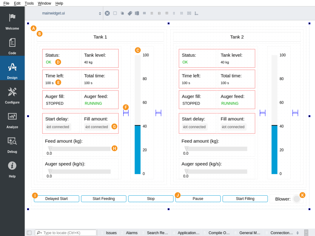
Look at the image above and create a similar GUI. The following table lists the widgets along with configuration tips:
| Widget | Description |
|---|---|
| Widget | The Widget is a transparent container that includes the most basic of widget functionality. We often use it to group content instead of ordinary layouts as it includes properties for controlling maximum and minimum size. To set a layout on the widget, click it and then select layout type from the tool menu above the form. This is also how you'll set the main layout on the CDPBaseMainWindow (the main widget in the form). Start your design by adding two QWidgets in a vertical layout. Make the top widget expanding by adjusting the size policy. Then add two more QWidgets to the top widget in a horizontal layout. Now, we can start adding elements. Note: Holding down CTRL while dragging an element with the left mouse button will make a copy of the dragged element. |
| Horizontal Line and Label | Create a title element by adding two Horizontal Line elements and one Label into a widget. Set a vertical layout and adjust all margins to zero. Note that we sometimes add a maximum size to the Horizontal Line elements. This is to ensure a fixed size no matter the size calculations done by the framework, but it shouldn't be necessary in this example. |
| Vertical Bar | Configure the bar similar to the image. Use the numPos property to enable numbers and adjust the amount of numbers by adjusting majorTicks. This works even though the ticks are not visible. Also, note properties like numTickOffset, tickBarSpacing and end margins that can be used to position texts and bar endings. Note: The color of the bar can be changed by adjusting the widget style. |
| Text Selector | This widget is used for showing different texts based on text or numeric value. Add texts to the selector by right-clicking and selecting "Edit Items..." in the context menu. By default, index numbers are used to trigger the different texts, starting at value 0. Enable text coloring by toggling the useIndexColor property and setting colors to the color properties named index0 and so on. |
| Label | A Label configured with text aligned to the left and a postfix that will get appended to any received value. Note: To add an ordinary layout, outlined in red strokes, select the widgets by left-clicking with the mouse while holding down CTRL. Then, select one of the layouts from the toolbox just above the form. Be aware that the widgets cannot already be in a layout if wanting to do this. |
| Spacer | Use spacers to allow certain areas in the form to expand when the size of the form is resized. Note: To add an ordinary layout, outlined with red strokes, select widgets by left-clicking with the mouse while holding down CTRL. Then, select one of the layouts from the toolbox just above the form. Be aware that the widgets cannot already be in a layout if wanting to do this. |
| Line Edit | The Line Edit is configured similar to the Label, but can also take input from the user. Note: Use the padType property if you want to pop up a numeric GUI keyboard instead of using a physical one. When padType is specified, the relevant keyboard appears whenever the user selects the Line Edit. |
| Slider | The Slider is configured with Horizontal orientation and type set to TriangleKnob. The knob text requires some tweaking to get the look we want. Use properties like minimumSize, knobTextRect, endMargins and tickRailEndAlignment to make it look like the example. |
| Message Button | All buttons except the one in are configured in the same way, to send messages to the control system. |
| Message Button | This button is configured to be checkable and to toggle the paused state of the control application. Make sure that checkableByClick is set and use the property named cdpCheckedRouting when adding the path to the remote object. |
| Lamp | The Lamp is a simple lamp to show on and off states. Use the maximumSize property to set a proper size. |
Route the Tank Widgets
We have now added the various widgets, but they are not yet associated with our CDP components in any way. The different display and input widgets will all be connected to specific CDP signals via routings.
- Select a widget that you want to route to a signal
- In the menu on the right hand side, enter “cdpRouting” in the Filter textbox
- Set the "cdpRouting" property value to the appropriate CDP signal, so that the routing follows this structure: "ApplicationName.ComponentName.SignalName.Value"
For example to display the tank level of FishTank1 with the Vertical Bar widget, we set the routing to be FishTankControlApp.FishTank1.TankLevel.Value
Note: Make sure to set the routing to be the full path to the signal that you wish to route to. For example if the signal is located in a component, that is not directly under the application but has a parent component of its own (see schema below), the routing might look something like this instead: "ApplicationName.ComponentName.SubComponent.SignalName.Value".
SystemName
    ∟ApplicationName
        ∟ComponentName
            ∟SubComponent
                ∟SignalName
                ∟SignalName2
                ∟SignalName3
            ∟SubComponent2
            ∟SubComponent3
        ∟ComponentName2
            ∟SubComponent4
Also note that the system's name is never in the routing.
Do this for all tank widgets and refer to the following tables for guidance.
Tank 1 (replace FishTank1 with FishTank2 when routing the widget for Tank 2):
| Widget | cdpRouting |
|---|---|
| Status | FishTankControlApp.FishTank1.AlarmStatus.Value |
| Tank level (bar and text) | FishTankControlApp.FishTank1.TankLevel.Value |
| Time left | FishTankControlApp.FishTank1.RemainingTime.Value |
| Total time | FishTankControlApp.FishTank1.TimeFeeded.Value |
| Auger fill | FishTankControlApp.FishTank1.FillScrewActive.Value |
| Auger feed | FishTankControlApp.FishTank1.ScrewActive.Value |
| Start delay | FishTankControlApp.FishTank1.StartTime.Value |
| Fill amount | FishTankControlApp.FishTank1.FillAmount.Value |
| Feed amount | FishTankControlApp.FishTank1.FeedAmount.Value |
| Auger speed | FishTankControlApp.FishTank1.ScrewSpeed.Value |
Route the Buttons
All buttons except the one that pauses feeding are set up to send messages. This is done using the following properties:
- Set the "cdpRouting" property to the component we want to send a message to
- Set the "cdpTextCommand" property to the message we want to send to the component
All buttons, that are common for both FishTanks send messages through the GuiInterface component. Other buttons send messages directly to the associated FishTank. The following table lists the different routings should you get stuck:
| Widget | cdpRouting | cdpTextCommand |
|---|---|---|
| Delayed Start | FishTankControlApp.GuiInterface | AutoStartFeeding |
| Start Feeding | FishTankControlApp.GuiInterface | StartFeeding |
| Stop | FishTankControlApp.GuiInterface | Stop |
| Start Filling | FishTankControlApp.GuiInterface | StartFilling |
The button for pausing feeding does not send messages like the other buttons. Instead it toggles a signal when it gets checked. This is done using the following properties:
| Widget | cdpCheckedRouting |
|---|---|
| Pause | FishTankControlApp.GuiInterface.Pause.Value |
The blower lamp is not a button, but a plain lamp. The property for routing this widget depends on how the SVG file is structured. The properties, cdpRouting and cdpStyleRouting are used to select row and column in the svg. In the current version of the lamp widget, we use the following:
| Widget | cdpStyleRouting |
|---|---|
| Blower lamp | FishTankControlApp.FishTank1.BlowerActive.Value |
How to Run the Example
To run the example from CDP Studio, open Welcome mode and find it under Examples. Next, in Configure mode right-click on the library project and select Build, then right-click on the system project and select Run & Connect. See the Running the Example Project tutorial for more information.
Test Your System
After you have completed all the steps above, you should be ready to test out your new fishtank controller.
- Set the "Start delay" time to 5 seconds
- Click the "Delayed Start" button
- After 5 seconds the tank levels should start to decrease and augers should be running.
- If you then click the "Pause" button, then the tank levels should stop decreasing
- Clicking the "Pause" button again will resume the feeding process
- Change the feeding speed by adjusting the auger speed slider
- Click "Stop" to end the feeding process
- Enter 10 for the first tank's fill amount and 20 for the second tank's fill amount.
- Click the "Start Filling" button and verify that the tank levels increase.
- Click "Stop" to end the filling process
As a result the GUI you created should appear in a newly opened window and after a couple of seconds it should connect to the FishTankControlApp. You can then try out if your system works as expected by playing around in the GUI. If it does not behave as expected, make sure you have done everything that was explained in this tutorial and if you are still having problems, then take a look at the source code of the example that is provided along with CDP.
Files
Get started with CDP Studio today
Let us help you take your great ideas and turn them into the products your customer will love.