Using Kinematics to Motion-Compensate Crane on the Moving Platform
Using Kinematics to Motion-Compensate Crane on the Moving Platform
The following example shows how to use CDP to create a controller for a crane, that stands on a moving platform (for example a ship), to control the speed-controlled crane motors to hold the crane in the desired position. In addition, the same controller can hold a carriage in the desired orientation despite the crane boom rotations. All this can be created using the CDP DHChain component, using the no-code approach.
The Crane Model
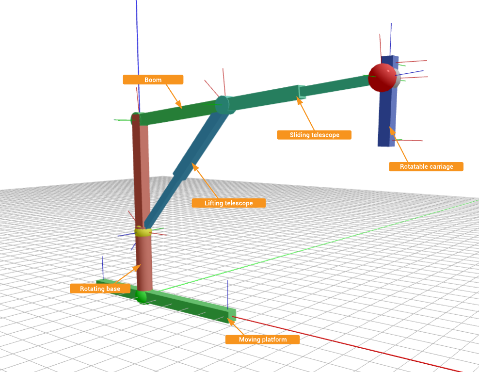
The crane consists of a base tower, that can freely rotate around its joint axis, a boom with sliding telescope, that is connected to the base, and a lifting cylinder, that can raise and lower the boom. A carriage is connected to the boom telescope end, which can be rotated by motors at 3 angles, allowing the carriage to be set to any orientation. The crane itself is mounted onto a moving platform.
To demonstrate the different controlling capabilities of the DHChain component, two types of motors are used in this example. Speed-controlled motors are used to move the crane and position-controlled motors are used to position the carriage.

How to Run the Example
To run the example from CDP Studio, open Welcome mode and find it under Examples. Next, in Configure mode right-click on the system project and select Run & Connect. See the Running the Example Project tutorial for more information.
How to Use The Example
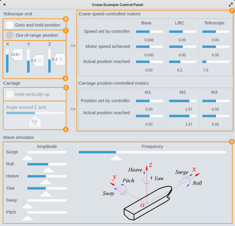
To make it easier to manipulate the crane and change platform movement simulation parameters, the example has also a GUI, looking like this:

From the GUI, the crane boom telescope end coordinates can be set and the crane can be instructed to go and hold there , despite the base platform movements. In cases when the coordinates can not be reached (because of the physical limitations of the crane) the DHChain component will enter into the Unsolved state and the corresponding alarm indicator will be shown in the GUI. Also, the crane will then stop trying to hold the position until the end coordinates are altered to some position that can be reached.
When the crane is instructed to hold the end position, the carriage can also be instructed to hold the upwards direction , despite the boom rotations. At the same time, it is possible to rotate the carriage around the Z-axis and the carriage will hold the desired orientation.
On the left side of the GUI there are indicators, that show the current speeds and positions reached for different crane arms and carriage motors .
On the bottom of the GUI, there are controls to alter the wave simulator parameters , that can be used to alter the nature of the platform movements.
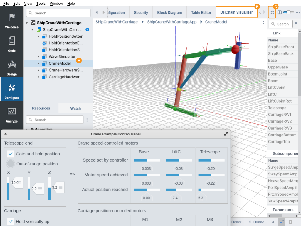
To better visualize the crane you should also switch to DHChain Visualizer in the CDP Studio, by selecting the CraneModel component and then switching to the DHChain Visualizer tab. When not all the links are fully visible you may need to click on the Fit in view button .

Functionalities of DHChain Used
The following useful functionalities of the DHChain are demonstrated by this example.
- The crane movements are created by using a MovingPosition port, that sets the position, angle and both linear and angular velocity for the crane base platform. The values are routed into it from WaveSimulator.
- To be able to calculate the crane lifting cylinder length, the cylinder end is connected to the base using PositionConstraint, thus creating a kinematic loop the DHChain can solve.
- To move (and hold) the crane in position, a PositionConstraint is added to the boom telescope end connected to a Position port. When the constraint port is connected, it instructs the DHChain to inverse calculate all the crane component lengths and also the movement speeds needed to hold the crane in the constraint position.
- To control the speed-controlled motors of the chain, a CalculatedThetaSpeed and CalculatedDSpeed output speed calculation elements are added to the chain moving links. These elements have also the PIDRegulator built-in, which is used to avoid the control resonance, which could otherwise easily happen because of the delay and inertia of the motors.
- To move (and hold) the carriage in position, a PositionConstraint added to a carriage is connected to the Angles port. When the constraint port is connected, it instructs the DHChain to inverse calculate all the carriage motor positions needed to keep the carriage at the angular position set.
- To prevent the boom telescope end from moving or accelerating at dangerously fast speed, MaxSpeed, MaxAcceleration and MaxDeceleration elements are added to the boom telescope DHLink, which are limiting the linear movement speed and also the linear acceleration and deceleration of the crane boom telescope end.
Other Components of the Example
In addition to the DHChain, the example consists of the following components:
- WaveSimulator - to simulate the crane platform movements on the sea. This simplified simulator is created using one Sine component and CDP operators to calculate different values of the simulator based on the Sine component output.
- CraneHardwareSimulator - to simulate the crane speed-controlled motor inertia and delay. This simplified simulator is created using CDP MinMaxLimiters, RampFilters, Delay and Evaluate operators. It gets desired motor speed values from DHChain controller, in input. It calculates the actual crane link positions reached considering the actual speed reached and hardware limitations, to output.
- CarriageHardwareSimulator - to simulate the carriage position-controlled rotation motors hardware. This simplified simulator is created using CDP RampFilters. It gets desired motor positions from DHChain controller, in input. It calculates the actual motor positions reached considering the hardware limitations, to output.
Get started with CDP Studio today
Let us help you take your great ideas and turn them into the products your customer will love.