Simulating Rotational Inverted Pendulum
Introduction
The purpose of this example is to demonstrate how a CDP Simulator project can make testing your automation system hardware independent in CDP Studio, the independent automation software for open PC-based real-time distributed control systems.
Consider a rod mounted on a horizontally rotating arm, such that the rod rotates freely in the normal plane of the arm. The arm motion is controlled by an external torque, in order to keep the rod in an upright position.

Rotary Inverted Pendulum (image courtesy, Quanser Inc. / © CC BY-SA 3.0)
Project Overview
This example includes:
- A library project containing two components:
- A regular CDP component called ArmController. It reads arm and rod angles as input and calculates the correct torque for the arm to keep the rod in the upright position.
- A simulator component called RotaryInvertedPendulumSimulator that makes this project independent from hardware. The rod and arm angles are simulated by RotaryInvertedPendulumSimulator using the torque of the arm as input.
- A system project containing three applications that may be deployed to either the same machine or different controllers. By default, they are configured to run on your local PC.
- Controller - contains the ArmController component created in the library project.
- Simulator - contains the RotaryInvertedPendulumSimulator component created in the library project and the SimulatorManager component which allows configuring some simulation properties.
- Graph - Includes a small plot to visualize the arm and rod angles. With default settings, both angles should become 0 rad once the rod is balanced.
Implementation Notes
The example is based on the Example 2: Rotary Inverted Pendulum described in the CDP Simulator manual.
Communication with the Control System
The project implements the Example 2: Rotary Inverted Pendulum described in the CDP Simulator manual with a small modification. Instead of directly Routing values between ArmController and RotaryInvertedPendulumSimulator, this example splits them into different applications and uses UDP I/O for communication. Presuming the real hardware can be controlled with UDP packets, this would enable hassle-free changing between the simulator and actual hardware as one can simply disconnect the hardware and instead run the simulator application. To get a better idea of how to configure UDPIOServer components, see the UDP Setup Guide.
Differential and Algebraic Equations
The RotaryInvertedPendulumSimulator component has implementations for both the EvaluateDiffEquations and EvaluateAlgebraicEquations methods. This means both ODE (ordinary differential equation) and DAE (differential-algebraic equations) solvers can be used. The method used depends on the SolverType property of the component which can be set in the Configure mode.
- The
EvaluateDiffEquationsmethod is used when the SolverType property is set toDifferential (ODE). In that case, an ODE (ordinary differential equation) solver is used to calculate the derivatives and do the integration. Note that the ODE solution is not allowed to contain Algebraic Loops, so the implementation of theEvaluateDiffEquationsmethod is a bit more complex. - The
EvaluateAlgebraicEquationsmethod is used when the SolverType property is set toAlgebraic. In that case, a DAE (differential-algebraic equations) solver is used which can handle Algebraic Loops, so the implementation of theEvaluateAlgebraicEquationsmethod is a bit simpler.
The derivation of is equations is described in the appendix of the CDP Simulator Examples page. See the Choosing an Integration Method manual for information on how to choose the right solver.
How to Run the Example
To run the example from CDP Studio, open Welcome mode and find it under Examples. Next, in Configure mode right-click on the library project and select Build, then right-click on the system project and select Run & Connect. See the Running the Example Project tutorial for more information.
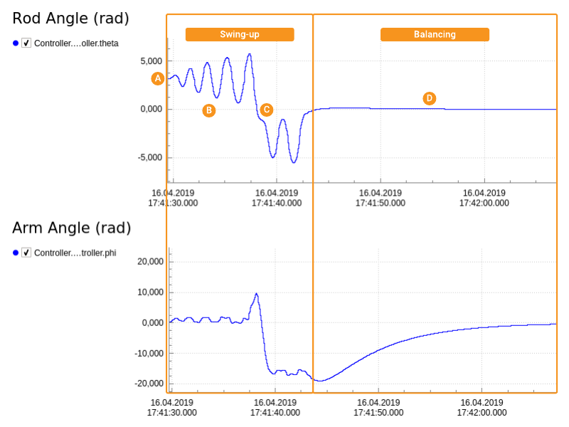
After running the project, a window opens which will plot the rod and arm angles. It will look something like this:
- The swing-up phase. At start-up () the rod is simply hanging, meaning its angle is π rad. Next, the arm will start swinging the rod () to get it to the upright position which is at the angle 0 rad. In this case, the swing-up was too aggressive and the rod did a full loop () meaning the new "down" position is -π rad. The swing-up continued until the rod was successfully balanced.
- The balancing phase (). Here the controller is balancing the rod in the upright position while moving the arm to the desired position, which is set by Controller.ArmController.phi_desired parameter in Configure mode. In this example, the desired arm position is 0 rad.
The example has also a DHChain component based visualizer included. When you locate and click on the Graph -> Visualizer node in the Project tree then you can see the pendulum visualized like this:
Integration Methods
When no integration method is specified, the SimulatorManager component defaults to using the Runge-Kutta Method for components where the SolverType is set to Differential (ODE) and SUNDIALS IDA for components where the SolverType is set to Algebraic.
To customize the integration method or to edit the default options, one must manually add an Integration Method from the Resource tree to the SimulatorManager component. See the Setting the Integration Algorithm section of the CDPSim manual for more information.
Read More
For further information on how the controller and simulator components were implemented, and the equations derived for the rotary inverted pendulum system, see the Example 2: Rotary Inverted Pendulum within the CDP Simulator manual.
Get started with CDP Studio today
Let us help you take your great ideas and turn them into the products your customer will love.